


1 引言
开关磁阻发电机(Switched Reluctance Generator,SRG)具有结构简单、控制灵活、可靠性高且容错能力强等优点,在中小功率风力发电和航空中的应用已引起国内外专家关注。开关磁阻发电机常见故障分为电机绕组故障、功率变换器故障、位置信号故障以及电源负载故障。文献[1]分析开关磁阻发电机在各种典型故障,通过仿真证明SRG具有很好的容错能力。文献[2]分析SRG运行特性,提出由2个控制器和2个功率变换器组成的双通道控制的双冗余控制策略,提高容错能力,但成本增加,双通道控制耦合严重。文献[3,4]通过改进双通道冗余控制的新型连接方案,进行双通道冗余解耦控制,但控制复杂、可靠性有待加强。
本文研究他励模式下开关磁阻发电机的功率变换器的开路和断路故障,提出一种基于续电流和相电流有效值的故障诊断策略,只需检测续流电流和相电流,不存在耦合,降低成本,提高故障诊断可靠性。
2 开关磁阻发电机工作原理
一个完整的开关磁阻发电机系统包括牵引部分、磁阻电机、功率变换器、控制模块和负载等。开关磁阻电机是SRG系统的执行元件。电机为双凸极结构,并且定、转子极数不相等。开关磁阻发电机的运动原理遵循“磁阻最小原理”——磁通总要沿着磁阻最小的路径闭合,而具有一定形状的铁心在移动到最小磁阻位置时,必使自己的主轴线与磁场的轴线重合。图1所示为一台3相12/8极开关磁阻电机示意图。
图1
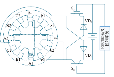
图1
12/8极开关磁阻发电机原理图作为整个发电系统起着能量传输作用的功率变换器一般采用三相不对称结构,按照开关磁阻发电机的工作模式,功率变换器又可以分为他励模式和自励模式。他励模式的功率变换器结构如
Fig.1
Diagram of the 12/8 pole SRG
图2
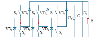
图2
三相不对称半桥功率变换器主电路
Fig.2
Schematic representation of an asymmetric IGBT bridge invertersupplying a three-phase SRG
开关磁阻发电机有励磁和发电两个阶段:
励磁阶段
发电阶段
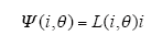
相绕组磁链为Ψ(i,θ),相绕组电感为L(i,θ),则
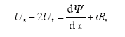
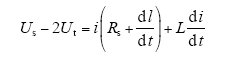
可得SRG励磁电压方程
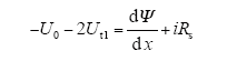
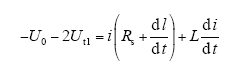
发电电压方程
式(4)和式(5)可改写成:
励磁阶段
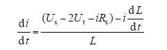
发电阶段
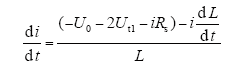
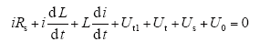
式中,Us为电源电压;U0为发电阶段输出电压;i为相绕组电流;Ut、Ut1为励磁、发电时的开关导通压降;L为相绕组电感。SRG电磁转矩为

可见,当转子在电感上升区间时,即 

3 他励SRG功率变换器故障类型分析
他励模式下SRG功率变换器主电路选用三相不对称半桥结构(见图2)。由于SRG各相独立,选一相分析。
3.1 上开关器件短路故障
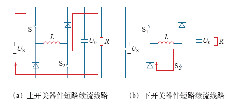
当S1短路、S2正常时,励磁正常,相电感L的相电流i、扭矩不受影响。励磁结束,短路故障改变该相续流路径:不通过续流二极管续流,其电流为零,可作为开关器件短路故障特征,如图3a所示。续流阶段电流、电压关系为
3.2 下开关器件短路故障
S1正常、S2短路时,S1通过斩单闸管策略控制绕组相电流,励磁正常。续流阶段S2无法关断,与续流二极管形成续流回路,如图3b所示。此时的电压、电流关系为
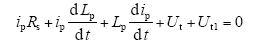
式中,ip、Lp为下开关器件短路形成环流和相电感电流。
图3
在电感下降区( 
3.3 开路故障
无论是上开关器件开路,还是下开关器件开路,都将导致该相无法正常励磁,SRG缺相运行,输出功率变低,该相中所有可测电流信号都变为零,虽然可作开路故障特征检测,但无法定位到开路开关器件。
4 基于特征值的故障诊断
针对他励模式下SRG功率变换器故障,提出的续电流和相电流有效值诊断算法。只需检测每相的续流二极管电流,综合考虑相电流,找到诊断特征值,通过逻辑判断部分,即可诊断出故障相,并定位到具体开关器件。
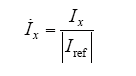
式中,Ix、Iref为相电流和参考值。续电流无参考值,且
考虑SRG角速度周期、开通区间等,采样周期T按下式选定
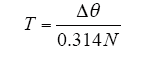
式中,开通区间Δθ = θoff - θon;N为发电机转速。
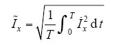
诊断参数可由各相续电流和相电流得到
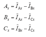
式中,x取值为1或者2。当x = 1时,得到续电流诊断参数;当x = 2时,得到为续电流诊断参数。
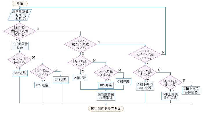
开关器件故障导致的续电流和相电流变化,通过逻辑判断可判别故障类型并实现故障器件定位,逻辑判断如图4所示。为了控制器依据诊断参数可以准确判断出故障类型和故障器件,设置3个判断阀值K1、K2和K3(K2>K1>K3)。K1用于检测开路的故障相;K2用于检测下开关器件短路的故障相;而K3用于检测上开关器件的短路故障。根据发电功率、诊断算法选取阀值,经过反复实验,本算法经验值公式为
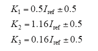
图4
5 Simulink仿真及实验
5.1 Simulink平台仿真
在Simulink仿真平台,依据开关磁阻发电机数学模型,建立SRG仿真模型,进行仿真实验。参数设置如下:12/8极三相SRG,额定转速为1 500r/min,开通角为22.5°,关断角为40°,参考电流值为6A。
图5
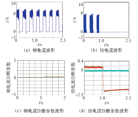
图5
上开关器件短路仿真结果
Fig.5
Simulation results of the upper switching device short-circuit fault
图6
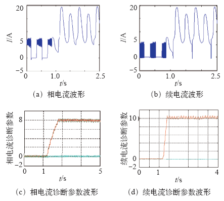
图6
下开关器件短路仿真结果
Fig.6
Simulation results of the down switching device shortcircuit fault
t = 2s时,A相发生开路故障,无法励磁,进入缺相运行状态,相电流和续电流马上降为零,如图7a和7b所示,可直接检测开路故障相。
图7
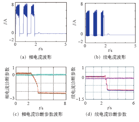
图7
开关器件开路仿真结果
Fig.7
Simulation results of the switching device open-circuitfault
5.2 硬件平台实验
图8
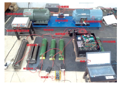
图9
5.2.1 IGBT短路故障
图10
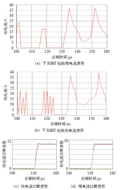
图10
下开关器件短路波形及诊断波形
Fig.10
Waveforms of diagnostic and currentsofdown IGBT short-circuitfault
上位机监控软件检测到诊断参数的绝对值超过检测阀值K3 = 3,故障特征明显,如图10d所示。由诊断软件可知,A相上开关器件发生短路故障。
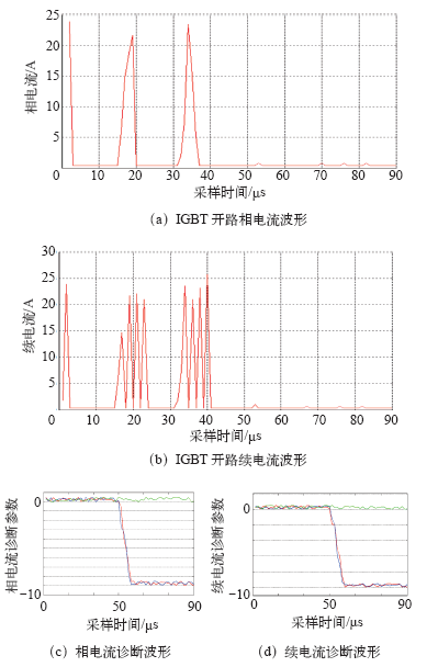
5.2.2 IGBT开路故障
图11
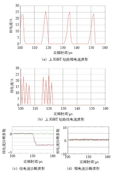
图11
上IGBT 短路波形及诊断波形
Fig.11
Waveformsof diagnostic and currents ofthe upper IGBT short-circuitfault
图12
图12
IGBT 开路波形及诊断波形
Fig.12
Waveformsof diagnostic and currents of IGBT opencircuit fault
在实验过程中,系统很容易检测到开路故障相,但由于无法在线修复,系统可以适当地增大其他相的开通区间,增大励磁电流来维持系统的输出效率。
6 结论
针对他励模式SRG功率变换器开关器件常见故障,本文分析了故障下续电流和相电流的变化关系,提出一种基于续电流和相电流有效值的诊断算法。只需在下续流二极管处增加一个电流传感器,通过参数值的提取和故障逻辑判断部分,实现故障检测和定位,节约成本。并提出3个阀值的经验公式,对其他应用的SRG具有指导作用。
参考文献
开关磁阻发电系统的故障分析及仿真
[J].
Fault analysis and simulation for the switched reluctance generator system
[J].
Two-channel switched reluctance starter/generator results
[J].DOI:10.1109/28.720442 URL [本文引用: 2]
航空开关磁阻发电机双通道容错性能研究
[J].
Research on fault-tolerant performance of dual-channel of aviation switched reluctance generator
[J].
双通道开关磁阻发电机建模及故障仿真研究
[J].
DOI:10.1016/j.ijpharm.2019.118994
URL
PMID:31893543
[本文引用: 2]

Lubricants are important for both preserving the tooling of high-speed tablet presses and attaining quality tablets. Magnesium stearate (MgSt) is most commonly used due to its superior lubrication efficiency; however, it can lead to negative effects on tabletability and dissolution. In this study, we have systematically evaluated two poloxamers, P188 and P407, for their suitability as alternative tablet lubricants. For two excipients with different mechanical properties, i.e., microcrystalline cellulose and lactose, both poloxamers exhibit acceptable lubrication efficiency without negatively impacting tabletability. Compared to 1% MgSt, the performance of both poloxamers at 2% in an experimental tablet formulation of ritonavir led to better lubrication, higher tabletability, and enhanced in vitro drug release. Thus, the use of P188 and P407 as alternative tablet lubricants deserves further evaluations.
Modeling and fault simulation of dual-channel switched reluctance generator
[J].
DOI:10.1016/j.ijpharm.2019.118994
URL
PMID:31893543
[本文引用: 2]
Lubricants are important for both preserving the tooling of high-speed tablet presses and attaining quality tablets. Magnesium stearate (MgSt) is most commonly used due to its superior lubrication efficiency; however, it can lead to negative effects on tabletability and dissolution. In this study, we have systematically evaluated two poloxamers, P188 and P407, for their suitability as alternative tablet lubricants. For two excipients with different mechanical properties, i.e., microcrystalline cellulose and lactose, both poloxamers exhibit acceptable lubrication efficiency without negatively impacting tabletability. Compared to 1% MgSt, the performance of both poloxamers at 2% in an experimental tablet formulation of ritonavir led to better lubrication, higher tabletability, and enhanced in vitro drug release. Thus, the use of P188 and P407 as alternative tablet lubricants deserves further evaluations.
A new method for power converter fault diagnosis in SRM drives
[J].
DOI:10.1109/TIA.2011.2180876
URL
This paper presents a new fault diagnostic technique applied to switched reluctance motor drives, based on the analysis of the power converter supply current. A fault is detected when the measured amplitude of the dc bus current differs from its expected amplitude, assuming normal operating conditions. The information about phase currents amplitudes and the control commands of all power switches permit to easily estimate the amplitude of the power converter supply current, since an asymmetric bridge converter is used. Simulation and experimental results are presented. Open- and short-circuit fault occurrences in the converter power switches are considered and analyzed. The proposed technique can early detect these fault occurrences and can also identify the affected motor phase. In almost all situations, the faulty element is also identified. An early fault diagnosis, with an accurate fault identification, is of a paramount importance since it permits the early adoption of fault-tolerant procedures that minimize the fault impact on the machine operation.
A new diagnostic technique for real-time diagnosis of power converter faults in switched reluctance motor drives
[C].
A new diagnostic technique for real-time diagnosis of power converter faults in switched reluctance motor drives
[J].
DOI:10.1109/TIA.2013.2279898
URL
[本文引用: 1]
Accurate fault identification allows the adoption of procedures that minimize the fault impact on the machine operation. Switched reluctance motors (SRMs) have been recognized for their fault-tolerant capabilities, and they present a very robust configuration, particularly due to the absence of windings or magnets in the rotor. All these attributes make the SRM a competitive solution for aircraft and automotive applications, where system reliability is a crucial feature. Therefore, in this paper, a new algorithm for real-time diagnosis of power converter faults in SRM drives is proposed. In contrast to other methods that use additional sensors or devices, the presented technique uses the measured phase currents only, which are already available for the drive control. The proposed algorithm effectively detects the inverter faulty phase and is capable of localizing the faulty power switch. Power switch open-and short-circuit fault occurrences in an asymmetric full-bridge converter are considered and analyzed.
Power converter fault diagnosis in SRM drives based on the DC Bus current analysis
[J].
Fault tolerant control of adjustable speed switched reluctance motor drives
[J].