1 引言
目前,市面上的无线充电产品大多为单负载无线充电方式,但是单负载充电方式存在对特定终端产品适配问题,“一对一”的无线充电模式逐渐不能满足人们的生活需求[1 -2 ] ,采用多负载无线充电系统能够充分利用能量并且支持不同终端产品[3 -4 ] 。同时,由于磁耦合谐振式无线充电系统的高效性、方便性与可靠性,因此适用于多负载无线充电系统[5 ] 。磁耦合无线充电系统在过耦合[6 ] 时会产生频率分叉现象,而频率分叉现象会使系统输出特性受到严重影响[7 ] ,因此有效规避频率分叉现象是提高系统传输效率的重点。对于频率分叉现象的分析,目前现有的文献大多针对单负载且负载阻值一定的情况[8 ⇓ ⇓ ⇓ -12 ] ,对双负载以及负载变化情况的研究较少。文献[13 ]通过构建等效模型,得到了单发双收系统输出功率表达式,利用数学软件对频率分叉现象进行了定性讨论,由于其公式复杂,未能得到分叉频率具体表达式。文献[14 ]分析了接收线圈在不同传输距离下频率分叉对系统输出功率的影响,但其第二个线圈为中继线圈不带任何负载。文献[15 ]研究了工作在分叉谐振频率系统传输特性的影响因素,利用系统工作在分叉谐振频率时同样提供较高的传输效率,设计实现了同时对3个谐振频率的线圈进行充电。文献[16 ]对SS拓扑结构的“一对二”无线充电系统进行了频率分叉分析,得到了耦合系数一定的情况下系统规避频率分叉的负载最大值,但其只研究了负载变化对频率分叉条件的影响。文献[13 ⇓ ⇓ -16 ]都只是针对SS结构等简单拓扑结构进行分析,而S-LCL结构具备负载无关的恒定电压输出能力,具有较强的带负载能力[17 ] ,适合双负载无线充电系统。因此,本文选择对S-LCL拓扑的双负载谐振无线充电系统进行频率分叉问题的研究。
本文首先搭建了双负载等效电路,通过理论推导,得到双负载无线充电系统传输功率、系统效率与当前工作频率的表达式,然后进一步得到系统规避频率分叉现象所需要满足的条件以及分叉谐振频率的数学表达式。通过Matlab数据仿真对结果进行仿真分析,得到系统频率分叉临界点和输出特性随负载和耦合系数的变化规律。最后,搭建电路仿真模型和物理试验对所得结论进行试验验证。
2 基于S-LCL拓扑网络的双负载无线充电系统的建模分析
2.1 系统等效电路特性分析
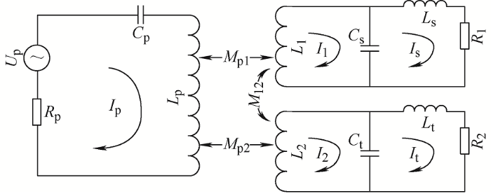
基于S-LCL谐振补偿的双负载无线充电系统的等效电路如图1 所示[18 ] ,其中R P 为发射端谐振电感内阻;L P 、C P 构成原边S型补偿网络结构;L S 、L 1 、C S 为第一个副边LCL补偿网络结构;L t 、L 2 、C t 为第二个副边LCL补偿网络结构;I P 为发射端输入电流;I 1 、I 2 为接收端输入电流;I S 、I t 为接收端输出电流;R 1 、R 2 为负载,M P1 、M P2 、M 12 为互感,k P1 、k P2 为耦合系数。
图1
为方便公式推导,给出S-LCL谐振网络相关参数表达式,如表1 所示。其中,相关参数有如下关系:L 1 =L S ;L 2 =L t ;${{\omega }_{1}}$ ${{\omega }_{2}}$ ${{\omega }_{P}}$ ${{\omega }_{0}}$
(1) $\left[\begin{array}{c}U_{\mathrm{p}} \\ 0 \\ 0\end{array}\right]=\left[\begin{array}{ccc}Z_{\mathrm{p}} & -\mathrm{j} \omega M_{\mathrm{p} 1} &-\mathrm{j} \omega M_{\mathrm{p} 2} \\ -\mathrm{j} \omega M_{\mathrm{p} 1} & Z_{\mathrm{s}} & \mathrm{j} \omega M_{12} \\ -\mathrm{j} \omega M_{\mathrm{p} 2} & \mathrm{j} \omega M_{12} & Z_{\mathrm{t}}\end{array}\right]\left[\begin{array}{c}I_{\mathrm{p}} \\ I_1 \\ I_2\end{array}\right]$
其中,原边线圈电路阻抗Z P ,副边线圈阻抗Z s 、Z t 分别为
(2) $\left\{ \begin{matrix} {{Z}_{\mathrm{p}}}=\text{j}\omega {{L}_{\mathrm{p}}}+\frac{1}{\text{j}\omega {{C}_{\mathrm{p}}}}+{{R}_{\mathrm{p}}}\begin{matrix} {} & {} & {} \\\end{matrix} \\ {{Z}_{\mathrm{s}}}=\text{j}\omega {{L}_{1}}+(\text{j}\omega {{L}_{\mathrm{s}}}+{{R}_{1}})//\frac{1}{\text{j}\omega {{C}_{\mathrm{s}}}} \\ {{Z}_{\mathrm{t}}}=\text{j}\omega {{L}_{2}}+(\text{j}\omega {{L}_{\mathrm{t}}}+{{R}_{2}})//\frac{1}{\text{j}\omega {{C}_{\mathrm{t}}}} \\\end{matrix} \right.$
(3) $\left\{ \begin{matrix} {{I}_{1}}=\frac{{{\omega }^{2}}{{M}_{\mathrm{p}2}}{{M}_{12}}+\text{j}\omega {{M}_{\mathrm{p}1}}{{Z}_{t}}}{{{Z}_{\mathrm{s}}}{{Z}_{t}}+{{\omega }^{2}}{{M}_{12}}^{2}}{{I}_{\mathrm{p}}} \\ {{I}_{2}}=\frac{{{\omega }^{2}}{{M}_{\mathrm{p}1}}{{M}_{12}}+\text{j}\omega {{M}_{\mathrm{p}2}}{{Z}_{\mathrm{s}}}}{{{Z}_{\mathrm{s}}}{{Z}_{t}}+{{\omega }^{2}}{{M}_{12}}^{2}}{{I}_{\mathrm{p}}} \\\end{matrix} \right.$
由式(1)和式(3)可以得到原边电压与电流的关系为
(4) $\begin{gathered}\dfrac{U_p}{I_p}=Z_p+Z_{p-s}= \\Z_{\mathrm{p}}+\frac{\omega^{2}({M_{p1}}^{2}Z_{\mathrm{t}}+M_{p2}^{2}Z_{s})+2\mathrm{j}\omega^{3}M_{p1}M_{p2}M_{12}}{Z_{s}Z_{1}+\omega^{2}{M_{12}}^{2}}\end{gathered}$
由于在双负载系统中接收线圈相对发射线圈较小,同时两接收线圈距离较远,故不考虑两个副边线圈之间的互感,即M 12 =0,根据式(3)和式(4)可以得到双负载系统的反射阻抗为
(5) ${{Z}_{\mathrm{p-s}}}=\frac{{{\omega }^{2}}M_{\text{p1}}^{2}}{{{Z}_{\mathrm{s}}}}+\frac{{{\omega }^{2}}M_{\text{p2}}^{2}}{{{Z}_{t}}}$
设${{\omega }_{\mathrm{n}}}=\omega /{{\omega }_{0}}$ ${{\omega }_{0}}$ $\omega $ ${{\omega }_{\mathrm{n}}}$ Z P-S 以实部R P-S 与虚部X P-S 的形式表示为
(6) $\left\{ \begin{matrix} {{R}_{\mathrm{P-S}}}=(k_{\mathrm{P}1}^{2}{{\alpha }_{1}}+k_{\mathrm{P}2}^{2}{{\alpha }_{2}})\omega {{L}_{\mathrm{P}}} \\ {{X}_{\mathrm{P-S}}}=(k_{\mathrm{P}1}^{2}{{\beta }_{1}}+k_{\mathrm{P}2}^{2}{{\beta }_{2}})\omega {{L}_{\mathrm{P}}} \\\end{matrix} \right.$
(7) ${{\alpha }_{i}}=\frac{{{\omega }_{n}}({{(1-\omega _{\mathrm{n}}^{2})}^{2}}+{{\omega }_{\mathrm{n}}}^{2}(2-\omega _{\mathrm{n}}^{2}))}{\frac{{{(1-{{\omega }_{\mathrm{n}}}^{2})}^{2}}}{{{Q}_{\mathrm{s}i}}}+\omega _{\mathrm{n}}^{2}{{Q}_{\mathrm{s}i}}{{(2-\omega _{\mathrm{n}}^{2})}^{2}}}$
(8) ${{\beta }_{i}}=\frac{(\omega _{\mathrm{n}}^{2}-1){{\omega }_{\mathrm{n}}}^{2}Q_{\mathrm{s}i}^{2}(2-{{\omega }^{2}})+\omega _{\mathrm{n}}^{\mathrm{2}}(1-\omega _{\mathrm{n}}^{\mathrm{2}})}{{{(1-{{\omega }_{\mathrm{n}}}^{2})}^{2}}+\omega _{\mathrm{n}}^{2}Q_{\mathrm{s}i}^{2}{{(2-\omega _{\mathrm{n}}^{\mathrm{2}})}^{2}}}$
式(7)、式(8)中$i=$ 1 ,2,将系统输出功率与传输效率用次级侧反映到初级侧的反射阻抗实部R P-S 与虚部X P-S 的方式表示[12 ]
(9) $\left\{ \begin{matrix} P=\frac{U_{\mathrm{P}}^{\mathrm{2}}{{R}_{\mathrm{P-S}}}}{{{({{R}_{\mathrm{P}}}+{{R}_{\mathrm{P-S}}})}^{2}}+{{(\omega {{L}_{\mathrm{P}}}-\frac{1}{\omega {{C}_{\mathrm{P}}}}+{{X}_{\mathrm{P-S}}})}^{2}}} \\ \eta =\frac{{{R}_{\mathrm{P-S}}}}{{{R}_{\mathrm{P}}}+{{R}_{\mathrm{P-S}}}}\begin{matrix} \begin{matrix} \begin{matrix} {} & {} & {} \\\end{matrix} & {} & {} \\\end{matrix} & {} & {} & {} \\\end{matrix} \\\end{matrix} \right.$
2.2 频率分叉条件分析
磁耦合谐振式无线充电系统产生频率分叉现象的原因是由于谐振电容的引入导致系统总阻抗虚部为0且存在多个解,从而使得系统在不同工况下出现多个谐振点[19 ] 。确定合适的工作参数范围使得系统在不会出现频率分叉现象的情况下工作是提高系统稳定性的一个关键点[16 ] 。本节通过分析系统达到谐振的条件来确定分叉谐振频率以及规避频率分叉的参数变化范围。为方便计算,频率分叉分析在R 1 =R 2 =R 条件下进行。
(10) ${{X}_{\mathrm{p}}}=\omega{{L}_{\mathrm{P}}}-\frac{1}{\omega {{C}_{\mathrm{P}}}}+{{X}_{\mathrm{P-S}}}=0$
当$\omega \text{=}{{\omega }_{0}}$ C P 的设计值为
(11) ${{C}_{\mathrm{P}}}\text{=}\frac{1}{{{\omega }_{0}}^{2}{{L}_{\mathrm{P}}}}$
将式(6)、式(11)代入式(10)化简得到发射端总阻抗虚部为0,即
(12) ${{X}_{\mathrm{p}}}=(\omega _{\mathrm{n}}^{2}-1)f({{Q}_{\mathrm{s}i}},{{k}_{\mathrm{p}1}},{{k}_{\mathrm{p}2}},{{\omega }_{\mathrm{n}}})=0$
(13) $f({{Q}_{\mathrm{s}i}},{{k}_{\mathrm{p1}}},{{k}_{\mathrm{p2}}},{{\omega }_{\mathrm{n}}})=a\omega _{\mathrm{n}}^{\mathrm{6}}+b\omega _{\mathrm{n}}^{\mathrm{4}}+c\omega _{\mathrm{n}}^{\mathrm{2}}+1$
(14) $a=[1-(k_{\text{p1}}^{2}+k_{\text{p2}}^{2})]Q_{\mathrm{s}i}^{\mathrm{2}}$
(15) $b=[2(k_{\text{p1}}^{2}+k_{\text{p2}}^{2})-4]Q_{\mathrm{s}i}^{\mathrm{2}}-(k_{\text{p1}}^{2}+k_{\text{p2}}^{2})+1$
(16) $c=4Q_{\mathrm{s}i}^{\mathrm{2}}-2$
需要保证系统只在${{\omega }_{0}}$ ${{\omega }_{\mathrm{n}}}=1$ $x=\omega _{\mathrm{n}}^{\mathrm{2}}$ x 的一元三次函数$f(x)=a{{x}^{3}}+b{{x}^{2}}+cx+1=0$ k p1 、k p2 在实际应用中远小于1,即$a>0$ $f(0)=1>0$ ${f}'(x)$ $f(x)$ $f(x)$ $x>0$
(17) $f{{(x)}_{\min }}=f\left( \frac{-2b+\sqrt{{{(2b)}^{2}}-4\times 3a\times c}}{2\times 3a} \right)>0$
根据式(14)~(17)推导出S-LCL谐振网络的双负载无线充电系统不出现频率分叉的边界条件为
(18) ${{Q}_{\mathrm{s}i}}>\sqrt{\frac{9(1-(k_{\mathrm{p}1}^{2}+k_{\mathrm{p}2}^{2}))(2{{(k_{\mathrm{p}1}^{2}+k_{\mathrm{p}2}^{2})}^{2}}-22(k_{\mathrm{p}1}^{2}+k_{\mathrm{p}2}^{2})+1)}{216(6-4(k_{\mathrm{p}1}^{2}+k_{\mathrm{p}2}^{2})){{(k_{\mathrm{p}1}^{2}+k_{\mathrm{p}2}^{2})}^{2}}}}$
系统工作状态需要满足式(18)才能避免频率分叉现象。在电路参数固定的情况下,根据式(18)得到频率分叉现象的主要影响因素为负载阻值R 以及耦合系数k p1 、k p2 。
根据式(12)得到$f({{\omega }_{\mathrm{n}}}^{2})=0$
(19) $f({{\omega }_{\mathrm{n}1}})=\frac{{{\omega }_{0}}}{2\mathrm{ }\!\!\pi\!\!\text{ }}\sqrt{-\frac{b}{3a}+\frac{-\sqrt{3}j-1}{2}\sqrt[3]{\frac{bc}{6{{a}^{2}}}-\frac{{{b}^{3}}}{27{{a}^{3}}}-\frac{1}{2a}+\sqrt{\Delta }}+\frac{\sqrt{3}j-1}{2}\sqrt[3]{\frac{bc}{6{{a}^{2}}}-\frac{{{b}^{3}}}{27{{a}^{3}}}-\frac{1}{2a}-\sqrt{\Delta }}}$
(20) $f({{\omega }_{\mathrm{n}2}})=\frac{{{\omega }_{0}}}{2\mathrm{ }\!\!\pi\!\!\text{ }}\sqrt{-\frac{b}{3a}+\sqrt[3]{\frac{bc}{6{{a}^{2}}}-\frac{{{b}^{3}}}{27{{a}^{3}}}-\frac{1}{2a}+\sqrt{\Delta }}+\sqrt[3]{\frac{bc}{6{{a}^{2}}}-\frac{{{b}^{3}}}{27{{a}^{3}}}-\frac{1}{2a}-\sqrt{\Delta }}}$
(21) $\Delta ={{\left( \frac{bc}{6{{a}^{2}}}-\frac{{{b}^{3}}}{27{{a}^{3}}}-\frac{1}{2a} \right)}^{2}}+{{\left( \frac{c}{3a}-\frac{{{b}^{2}}}{9{{a}^{2}}} \right)}^{3}}$
结合式(14)~(16)得到影响分叉谐振频率的因素有k p1 、k p2 以及Q s i L p 、L 1 、L 2 和M p1 、M p2 以及R 。
3 仿真与分析
3.1 系统参数设计
设定原边线圈等效电感值为329.88 μH,系统各参数数值如表2 所示。
3.2 频率分叉条件仿真分析
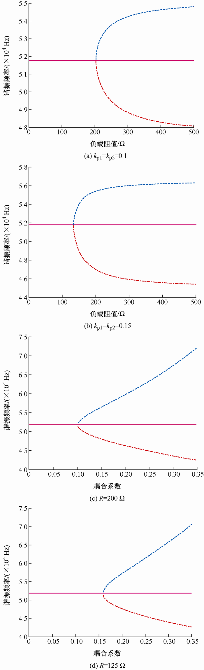
将表2 的各项数据代入式(19)、式(20),在R 2 =R 1 =R 的条件下,利用Matlab软件得到如图2 所示的分叉仿真图形,图2 中实线为系统谐振频率,点划线为$f({{\omega }_{\mathrm{n1}}})$ $f({{\omega }_{\mathrm{n2}}})$ 图2a 、2b 是在k p1 、k p2 固定条件下不同负载的频率分叉情况,图2c 、2d 是在负载阻值R 固定条件下不同负载的频率分叉情况,可以看出k p1 =k p2 =0.1时负载不产生频率分叉的临界值为R =200 Ω,k p1 =k p2 =0.15时负载不产生频率分叉的临界值为R =125 Ω,根据式(20)得到k p1 =k p2 =0.15时理论值为122.9 Ω,k p1 =k p2 =0.1时理论值为204.5 Ω,仿真值符合理论值。从图2b 可以看出,S-LCL结构在携带远大于临界负载谐振频率的负载时,其分叉谐振频率基本保持不变。同时在S-LCL双负载谐振网络中,负载阻值减小则系统频率分叉临界耦合系数增大;而在SS结构中,负载阻值减小,系统频率分叉临界耦合系数减小[8 ] ,S-LCL结构的变化趋势和SS结构相反。因此S-LCL结构在耦合系数较小的情况下频率分叉临界负载比SS结构大,具有更强的带负载能力。
图2
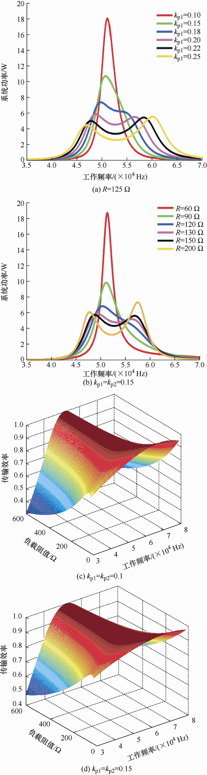
将表2 中数据代入式(9),从系统输出特性的角度来分析频率分叉现象,如图3 所示。
图3
图3
双负载S-LCL谐振网络输出特性频率分叉现象
从图3a 、图3b 可以看出,负载以及耦合系数的增大会导致输出功率曲线产生频率分叉现象,谐振频率点${{\omega }_{0}}$
从图3c 、3d 可以看出,负载以及耦合系数的变化不会导致系统效率出现双峰的情况。对比图3c 、图3d 可得,耦合系数的增加会减缓工作频率的变化对系统效率的影响。
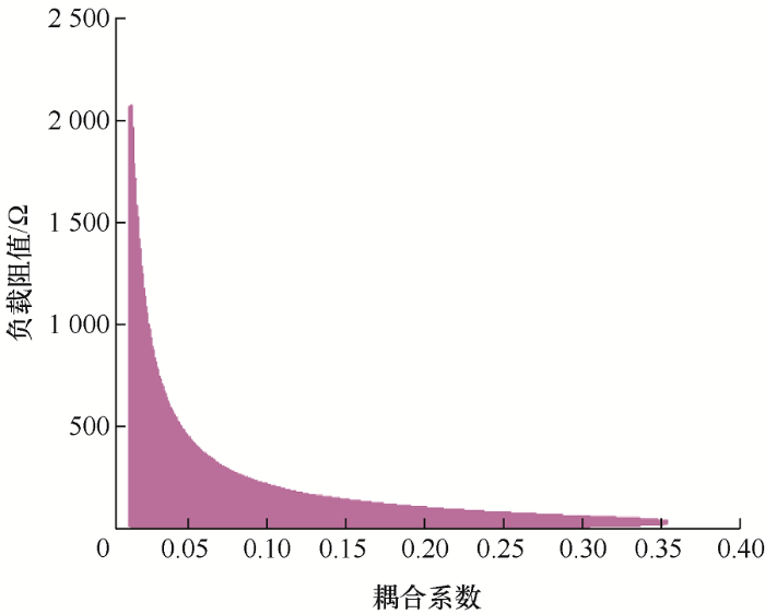
将表2 中数据代入式(18),结果如图4 所示,当耦合系数以及负载取值满足图4 所示区域内系统不会产生频率分叉现象。从图4 可以看出,当耦合系数为0.1时,负载阻值临界点在200 Ω左右,耦合系数为0.15时,负载阻值临界点在125 Ω左右,符合图2 的分析结果。
图4
图4
双负载S-LCL谐振网络耦合系数与负载取值范围
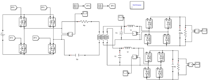
为验证所得到有关S-LCL谐振网络频率分叉结论的正确性,根据表2 中的电路参数,利用Matlab/Simlulink软件搭建无线充电系统仿真电路模型,电路图如图5 所示。
图5
图5
Matlab/Simlulink电路仿真电路图
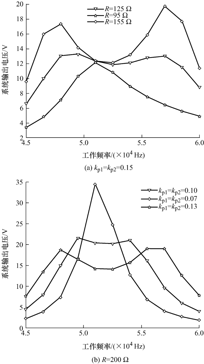
发射端电路由5 V直流电源、高频逆变电路和S型谐振网络构成;接收端电路由副边LCL型谐振网络、整流滤波稳压电路以及负载构成。在45~60 kHz的工作频率下,通过改变负载阻值或谐振线圈耦合系数,观察负载上的输出电压变化,得到不同情况下系统输出电压随工作频率的变化情况如图6 所示。
图6
图6a 、6b 中,当负载R 增大到125 Ω或者耦合系数K 增大到0.1时,系统输出电压曲线上出现了分叉现象,符合图4 中的取值范围。随着R /K 的增大,分叉现象越明显,分叉频率之间带宽不断增大,符合所得到的结论。从图6a 中曲线可知,在系统谐振频率下,耦合系数K 一定时,R 变化不会影响S-LCL谐振网络的输出电压变化且稳定在12 V,验证了S-LCL谐振网络具备恒压输出的特性[17 ] 。
4 试验验证
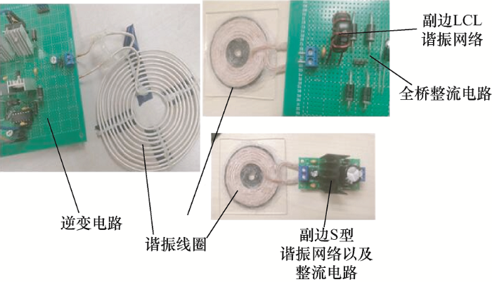
根据上述仿真的分析结果,搭建SS结构与S-LCL结构对比试验验证平台。试验电路如图7 所示,原副边线圈采用利兹线绕制而成,线圈参数如表3 所示。
图7
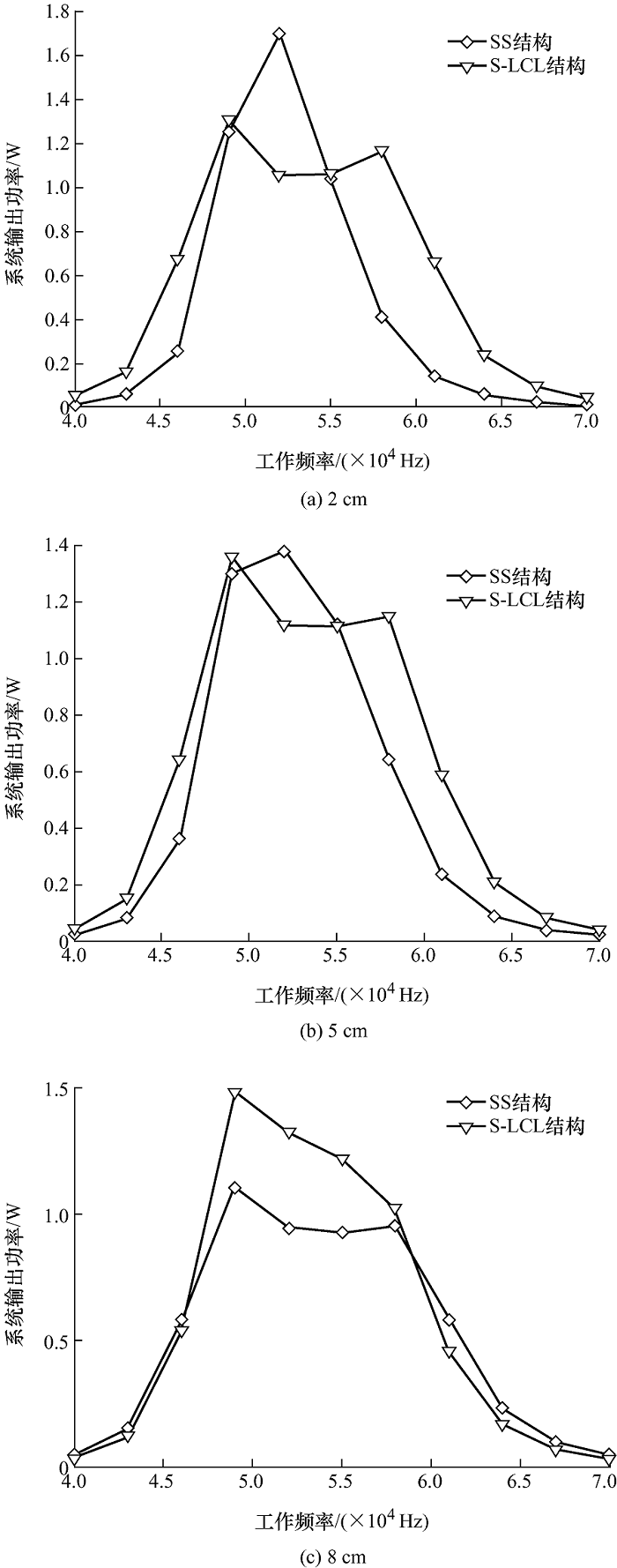
在实际试验中耦合系数较为难测量[20 ] ,选择改变原副边线圈之间间距模拟耦合系数变化的情况。系统输入电压为5 V,负载为100 Ω,对40~70 kHz工作频率下不同间距的系统进行试验,根据试验数据可以绘制图8 所示图形。图8 中,当线圈之间间距为2 cm时,耦合系数较大,只有S-LCL型谐振网络出现频率分叉现象;当间距为8 cm时,耦合系数较小,只有SS型出现频率分叉现象且S-LCL谐振网络的频率分叉现象消失。因此,随着耦合系数的逐渐减小,SS结构的分叉临界点逐渐减小,而S-LCL结构的分叉临界点逐渐增大。
图8
综上所述,相比SS结构,S-LCL结构更适合耦合系数较小的情况。
5 结论
本文对S-LCL双负载无线充电系统频率分叉条件进行了研究。首先搭建了双负载系统等效电路,推导得出系统反映阻抗、输出功率以及传输效率的数学表达式。利用阻抗相角零点条件推导得出能够规避频率分叉现象的条件,并得到影响分叉谐振频率的主要影响因素有L p 、L 1 、L 2 和M p1 、M p2 以及负载R 。设定电路参数,对理论结果进行仿真分析,得到如下结论。
(1) 对分叉谐振频率进行了仿真分析以及试验验证得到,对比SS结构,S-LCL结构在耦合系数较小的情况下频率分叉临界负载较大,具有更强的带负载能力。
(2) 从输出特性的角度对频率分叉的主要影响因素进行仿真分析。对于系统输出功率,系统在频率分叉区域有双峰输出特性,而在无分叉区域呈单峰输出特性。且随着频率分叉现象主要影响因素负载和耦合系数的增大,分叉谐振频率之间带宽增大。对于系统传输效率,影响因素的变化不会导致传输效率曲线出现双峰。
(3) 仿真得到可以规避频率分叉现象的负载-耦合系数的取值范围,明确其取值范围能够有效提高双负载S-LCL磁谐振无线充电系统的整体稳定性。
参考文献
View Option
[1]
戴英花 , 董林玺 . 一种带负载识别的多负载无线充电系统设计
[J]. 杭州电子科技大学学报 , 2016 , 36 (1 ):21 -26 .
[本文引用: 1]
DAI Yinghua DONG Linxi Design of a multi-load wireless charging system with load identification
[J]. Journal of Hangzhou Dianzi University , 2016 , 36 (1 ):21 -26 .
[本文引用: 1]
[2]
FAN S LIU Z FENG G et al . Dynamic process analysis and voltage stabilization control of multi-load wireless power supply system
[J]. Energies , 2021 , 14 (5 ):1466 .
DOI:10.3390/en14051466
URL
[本文引用: 1]
[3]
ZHANG Zhang ZHOU Xiaojuan XIE Yulei et al . Multi-load constant current charging technology for wireless charging system
[J]. International Journal of Electronics , 2020 , 107 (8 ):1254 -1271 .
DOI:10.1080/00207217.2020.1726487
URL
[本文引用: 1]
[4]
鲁丽航 , 宋卫平 , 宁爱平 , 等 . 双负载无线充电系统交叉耦合分析
[J]. 太原科技大学学报 , 2020 , 41 (4 ):264 -269 ,274.
[本文引用: 1]
LU Lihang SONG Weiping NING Aiping et al . Cross-coupling analysis of dual-load wireless charging system
[J]. Journal of Taiyuan University of Science and Technology , 2020 , 41 (4 ):264 -269 ,274.
[本文引用: 1]
[5]
LI Zhenjie ZHU Chunbo JIANG Jinhai et al . A 3-kW wireless power transfer system for sightseeing car supercapacitor charge
[J]. IEEE Transactions on Power Electronics , 2016 , 32 (5 ):3301 -3316 .
DOI:10.1109/TPEL.2016.2584701
URL
[本文引用: 1]
[6]
SAMPI A P MEYER D A SMITH J R Analysis,experimental result,and range adaptation of magnetically coupled resonators for wireless oower transfer
[J]. IEEE Trans. on Industrial Electronics , 2011 , 58 (2 ):544 -554 .
DOI:10.1109/TIE.2010.2046002
URL
[本文引用: 1]
[7]
李中启 , 黄守道 , 易吉良 , 等 . 磁耦合谐振式无线电能传输系统频率分裂抑制方法
[J]. 电力系统自动化 , 2017 , 41 (2 ):21 -27 .
[本文引用: 1]
LI Zhongqi HUANG Shoudao YI Jiliang et al . Suppression method for frequency splitting of magnetic coupling resonance wireless power transmission system
[J]. Automation of Electric Power Systems , 2017 , 41 (2 ):21 -27 .
[本文引用: 1]
[8]
李凤娥 . 磁共振无线电能传输系统最大传输距离的电路参数分析
[J]. 南昌航空大学学报 , 2012 , 26 (3 ):48 -51 ,62.
[本文引用: 2]
LI Fenge Analysis of the circuit parameters of the maximum transmission distance of the magnetic resonance wireless power transmission system
[J]. Journal of Nanchang Hangkong University , 2012 , 26 (3 ):48 -51 ,62.
[本文引用: 2]
[9]
杨世亮 , 汪宁 , 柳俊岗 , 等 . 磁耦合谐振串串式补偿结构分析
[J]. 自动化技术与应用 , 2020 , 39 (10 ):11 -13 ,30.
[本文引用: 1]
YANG Shiliang WANG Ning LIU Jungang et al . Analysis of string compensation structure of magnetic coupling resonant string
[J]. Technology of Automation and Applications , 2020 , 39 (10 ):11 -13 ,30.
[本文引用: 1]
[10]
郝会东 , 章小斌 , 郭咏 . 串并式无线电能传输系统的研究与设计
[J]. 电子设计工程 , 2019 , 27 (18 ):133 -137 .
[本文引用: 1]
HAO Huidong ZHANG Xiaobin GUO Yong Research and design of serial-parallel wireless power transmission system
[J]. Electronic Design Engineering , 2019 , 27 (18 ):133 -137 .
[本文引用: 1]
[11]
GUAN Z ZHANG B QIU D Influence of asymmetric coil parameters on the output power characteristics of wireless power transfer systems and their applications
[J]. Energies , 2019 , 12 (7 ):1 -19 .
DOI:10.3390/en12010001
URL
[本文引用: 1]
One of the benefits of the supercritical CO 2 Brayton cycle in Sodium-cooled Fast Reactors is an enhanced plant safety, since potential reactions of CO 2 with liquid sodium have been reported to be less stringent than a sodium-water reaction found in the Rankine cycle. However, moderate chemical interactions between CO 2 and liquid sodium make detecting CO 2 ingress accidents harder. Thus, this paper proposes a new physics-based detection algorithm by comparing the real-time pressure measurements of two identical heat exchangers for the early detection. The CO 2 ingress occurs owing to a crack at the pressure boundary wall, a certain self-recovery of structural damage does not happen over time, and an accident probabilistically starts at only one component of two. The proposed physics-based method with the probabilistic analysis was compared to the pure data-based method. Finally, the damage degradation was developed with a simplified mass and energy transfer model, and the proposed algorithm was verified with experimental data. The results show that a 99.99% detection probability can be achieved for the air ingress of 30 cc/s, which is equivalent to the 0.12 g/s CO 2 ingress, in a 70 s detection time, limiting down to 0.1% false alarms due to sensor noise.
[12]
MATTHEW S VIRGILIO V ANDREAS D Frequency splitting analysis and compensation method for inductive wireless powering of implantable biosensors
[J]. Sensors , 2016 , 16 (8 ):1229 -1242 .
DOI:10.3390/s16081229
URL
[本文引用: 2]
[13]
李炜昕 , 张合 , 李长生 , 等 . 磁耦合共振单发双收系统传输特性分析
[J]. 电工技术学报 , 2014 , 29 (2 ):191 -196 .
[本文引用: 2]
LI Weixin ZHANG He LI Changsheng et al . Analysis of transmission characteristics of magnetic coupling resonance single-transmit and double-receiving system
[J]. Transactions of China Electrotechnical Society , 2014 , 29 (2 ):191 -196 .
[本文引用: 2]
[14]
李新恒 , 龚立娇 , 冯力 , 等 . 三线圈磁耦合谐振式无线电能传输系统频率特性分析
[J]. 工矿自动化 , 2018 , 44 (3 ):91 -96 .
[本文引用: 2]
LI Xinheng GONG Lijiao FENG Li et al . Analysis of frequency characteristics of three-coil magnetic coupling resonance wireless power transmission system
[J]. Industry and Mine Automation , 2018 , 44 (3 ):91 -96 .
[本文引用: 2]
[15]
NARAYANAMOORTHI R JULIET A V BHARATIRAJA C Cross interference minimization and simultaneous wireless power transfer to multiple frequency loads using frequency bifurcation approach
[J]. IEEE Transactions on Power Electronics , 2019 :10898 -10909 .
[本文引用: 2]
[16]
雷阳 . 用于家用电器的双负载无线电能传输系统的研究 [D]. 哈尔滨 : 哈尔滨工业大学 , 2014 .
[本文引用: 3]
LEI Yang Research on dual-load wireless power transmission system for household appliances [D]. Harb in:Harbin Institute of Technology, 2014 .
[本文引用: 3]
[17]
王龙飞 . 基于S-LCL补偿的磁共振无线电能传输效率研究
[J]. 电力电子技术 , 2019 , 53 (6 ):23 -26 .
[本文引用: 2]
WANG Longfei Study on the efficiency of magnetic resonance wireless power transmission based on S-LCL compensation
[J]. Power Electronics , 2019 , 53 (6 ):23 -26 .
[本文引用: 2]
[18]
MENG X QIU D LIN M Output voltage identification based on transmitting side information for implantable wireless power transfer system
[J]. IEEE Access , 2018 , 7 :2938 -2946 .
DOI:10.1109/ACCESS.2018.2886424
URL
[本文引用: 1]
[19]
SHU X ZHANG B RONG C Frequency bifurcation in a series-series compensated fractional-order inductive power transfer system
[J]. Journal of Advanced Research , 2020 , 25 :235 -242 .
DOI:10.1016/j.jare.2020.04.010
PMID:32922990
[本文引用: 1]
This paper reveals and analyzes the frequency bifurcation phenomena in the fractional-order inductive power transfer (FOIPT) system with series-series compensation topology. Using fractional calculus theory and electric circuit theory, the circuit model of the series-series compensated FOIPT system is first proposed, then taking the case of a single variable fractional order as an example, three frequency analytical solutions of frequency bifurcation equation are solved by using Taylor expansion method. By analyzing the three bifurcation frequencies solved, it can be found that the frequency bifurcation phenomenon can be effectively eliminated by controlling the fractional order, and the boundary of critical distance and critical load is reduced, thereby expanding the working range of the conventional inductive power transfer (IPT) system. Furthermore, the output power and transfer efficiency at the three bifurcation frequencies are analyzed, it can be observed that the output power and transfer efficiency at the high bifurcation frequency and low bifurcation frequency are close and basically keep constant against the variation of transfer distance, and the output power is obviously higher than that at the intrinsic frequency. In addition, the output power at the three bifurcation frequencies can be significantly improved by adjusting the fractional order. Finally, the experimental prototype of FOIPT is built, and the experimental results verify the validity of theoretical analysis.© 2020 The Authors. Published by Elsevier B.V. on behalf of Cairo University.
[20]
WANG X YANG J A privacy image encryption algorithm based on piecewise coupled map lattice with multi dynamic coupling coefficient
[J]. Information Sciences , 2021 , 569 :217 -240 .
DOI:10.1016/j.ins.2021.04.013
URL
[本文引用: 1]
一种带负载识别的多负载无线充电系统设计
1
2016
... 目前,市面上的无线充电产品大多为单负载无线充电方式,但是单负载充电方式存在对特定终端产品适配问题,“一对一”的无线充电模式逐渐不能满足人们的生活需求[1 -2 ] ,采用多负载无线充电系统能够充分利用能量并且支持不同终端产品[3 -4 ] .同时,由于磁耦合谐振式无线充电系统的高效性、方便性与可靠性,因此适用于多负载无线充电系统[5 ] .磁耦合无线充电系统在过耦合[6 ] 时会产生频率分叉现象,而频率分叉现象会使系统输出特性受到严重影响[7 ] ,因此有效规避频率分叉现象是提高系统传输效率的重点.对于频率分叉现象的分析,目前现有的文献大多针对单负载且负载阻值一定的情况[8 ⇓ ⇓ ⇓ -12 ] ,对双负载以及负载变化情况的研究较少.文献[13 ]通过构建等效模型,得到了单发双收系统输出功率表达式,利用数学软件对频率分叉现象进行了定性讨论,由于其公式复杂,未能得到分叉频率具体表达式.文献[14 ]分析了接收线圈在不同传输距离下频率分叉对系统输出功率的影响,但其第二个线圈为中继线圈不带任何负载.文献[15 ]研究了工作在分叉谐振频率系统传输特性的影响因素,利用系统工作在分叉谐振频率时同样提供较高的传输效率,设计实现了同时对3个谐振频率的线圈进行充电.文献[16 ]对SS拓扑结构的“一对二”无线充电系统进行了频率分叉分析,得到了耦合系数一定的情况下系统规避频率分叉的负载最大值,但其只研究了负载变化对频率分叉条件的影响.文献[13 ⇓ ⇓ -16 ]都只是针对SS结构等简单拓扑结构进行分析,而S-LCL结构具备负载无关的恒定电压输出能力,具有较强的带负载能力[17 ] ,适合双负载无线充电系统.因此,本文选择对S-LCL拓扑的双负载谐振无线充电系统进行频率分叉问题的研究. ...
Design of a multi-load wireless charging system with load identification
1
2016
... 目前,市面上的无线充电产品大多为单负载无线充电方式,但是单负载充电方式存在对特定终端产品适配问题,“一对一”的无线充电模式逐渐不能满足人们的生活需求[1 -2 ] ,采用多负载无线充电系统能够充分利用能量并且支持不同终端产品[3 -4 ] .同时,由于磁耦合谐振式无线充电系统的高效性、方便性与可靠性,因此适用于多负载无线充电系统[5 ] .磁耦合无线充电系统在过耦合[6 ] 时会产生频率分叉现象,而频率分叉现象会使系统输出特性受到严重影响[7 ] ,因此有效规避频率分叉现象是提高系统传输效率的重点.对于频率分叉现象的分析,目前现有的文献大多针对单负载且负载阻值一定的情况[8 ⇓ ⇓ ⇓ -12 ] ,对双负载以及负载变化情况的研究较少.文献[13 ]通过构建等效模型,得到了单发双收系统输出功率表达式,利用数学软件对频率分叉现象进行了定性讨论,由于其公式复杂,未能得到分叉频率具体表达式.文献[14 ]分析了接收线圈在不同传输距离下频率分叉对系统输出功率的影响,但其第二个线圈为中继线圈不带任何负载.文献[15 ]研究了工作在分叉谐振频率系统传输特性的影响因素,利用系统工作在分叉谐振频率时同样提供较高的传输效率,设计实现了同时对3个谐振频率的线圈进行充电.文献[16 ]对SS拓扑结构的“一对二”无线充电系统进行了频率分叉分析,得到了耦合系数一定的情况下系统规避频率分叉的负载最大值,但其只研究了负载变化对频率分叉条件的影响.文献[13 ⇓ ⇓ -16 ]都只是针对SS结构等简单拓扑结构进行分析,而S-LCL结构具备负载无关的恒定电压输出能力,具有较强的带负载能力[17 ] ,适合双负载无线充电系统.因此,本文选择对S-LCL拓扑的双负载谐振无线充电系统进行频率分叉问题的研究. ...
Dynamic process analysis and voltage stabilization control of multi-load wireless power supply system
1
2021
... 目前,市面上的无线充电产品大多为单负载无线充电方式,但是单负载充电方式存在对特定终端产品适配问题,“一对一”的无线充电模式逐渐不能满足人们的生活需求[1 -2 ] ,采用多负载无线充电系统能够充分利用能量并且支持不同终端产品[3 -4 ] .同时,由于磁耦合谐振式无线充电系统的高效性、方便性与可靠性,因此适用于多负载无线充电系统[5 ] .磁耦合无线充电系统在过耦合[6 ] 时会产生频率分叉现象,而频率分叉现象会使系统输出特性受到严重影响[7 ] ,因此有效规避频率分叉现象是提高系统传输效率的重点.对于频率分叉现象的分析,目前现有的文献大多针对单负载且负载阻值一定的情况[8 ⇓ ⇓ ⇓ -12 ] ,对双负载以及负载变化情况的研究较少.文献[13 ]通过构建等效模型,得到了单发双收系统输出功率表达式,利用数学软件对频率分叉现象进行了定性讨论,由于其公式复杂,未能得到分叉频率具体表达式.文献[14 ]分析了接收线圈在不同传输距离下频率分叉对系统输出功率的影响,但其第二个线圈为中继线圈不带任何负载.文献[15 ]研究了工作在分叉谐振频率系统传输特性的影响因素,利用系统工作在分叉谐振频率时同样提供较高的传输效率,设计实现了同时对3个谐振频率的线圈进行充电.文献[16 ]对SS拓扑结构的“一对二”无线充电系统进行了频率分叉分析,得到了耦合系数一定的情况下系统规避频率分叉的负载最大值,但其只研究了负载变化对频率分叉条件的影响.文献[13 ⇓ ⇓ -16 ]都只是针对SS结构等简单拓扑结构进行分析,而S-LCL结构具备负载无关的恒定电压输出能力,具有较强的带负载能力[17 ] ,适合双负载无线充电系统.因此,本文选择对S-LCL拓扑的双负载谐振无线充电系统进行频率分叉问题的研究. ...
Multi-load constant current charging technology for wireless charging system
1
2020
... 目前,市面上的无线充电产品大多为单负载无线充电方式,但是单负载充电方式存在对特定终端产品适配问题,“一对一”的无线充电模式逐渐不能满足人们的生活需求[1 -2 ] ,采用多负载无线充电系统能够充分利用能量并且支持不同终端产品[3 -4 ] .同时,由于磁耦合谐振式无线充电系统的高效性、方便性与可靠性,因此适用于多负载无线充电系统[5 ] .磁耦合无线充电系统在过耦合[6 ] 时会产生频率分叉现象,而频率分叉现象会使系统输出特性受到严重影响[7 ] ,因此有效规避频率分叉现象是提高系统传输效率的重点.对于频率分叉现象的分析,目前现有的文献大多针对单负载且负载阻值一定的情况[8 ⇓ ⇓ ⇓ -12 ] ,对双负载以及负载变化情况的研究较少.文献[13 ]通过构建等效模型,得到了单发双收系统输出功率表达式,利用数学软件对频率分叉现象进行了定性讨论,由于其公式复杂,未能得到分叉频率具体表达式.文献[14 ]分析了接收线圈在不同传输距离下频率分叉对系统输出功率的影响,但其第二个线圈为中继线圈不带任何负载.文献[15 ]研究了工作在分叉谐振频率系统传输特性的影响因素,利用系统工作在分叉谐振频率时同样提供较高的传输效率,设计实现了同时对3个谐振频率的线圈进行充电.文献[16 ]对SS拓扑结构的“一对二”无线充电系统进行了频率分叉分析,得到了耦合系数一定的情况下系统规避频率分叉的负载最大值,但其只研究了负载变化对频率分叉条件的影响.文献[13 ⇓ ⇓ -16 ]都只是针对SS结构等简单拓扑结构进行分析,而S-LCL结构具备负载无关的恒定电压输出能力,具有较强的带负载能力[17 ] ,适合双负载无线充电系统.因此,本文选择对S-LCL拓扑的双负载谐振无线充电系统进行频率分叉问题的研究. ...
双负载无线充电系统交叉耦合分析
1
2020
... 目前,市面上的无线充电产品大多为单负载无线充电方式,但是单负载充电方式存在对特定终端产品适配问题,“一对一”的无线充电模式逐渐不能满足人们的生活需求[1 -2 ] ,采用多负载无线充电系统能够充分利用能量并且支持不同终端产品[3 -4 ] .同时,由于磁耦合谐振式无线充电系统的高效性、方便性与可靠性,因此适用于多负载无线充电系统[5 ] .磁耦合无线充电系统在过耦合[6 ] 时会产生频率分叉现象,而频率分叉现象会使系统输出特性受到严重影响[7 ] ,因此有效规避频率分叉现象是提高系统传输效率的重点.对于频率分叉现象的分析,目前现有的文献大多针对单负载且负载阻值一定的情况[8 ⇓ ⇓ ⇓ -12 ] ,对双负载以及负载变化情况的研究较少.文献[13 ]通过构建等效模型,得到了单发双收系统输出功率表达式,利用数学软件对频率分叉现象进行了定性讨论,由于其公式复杂,未能得到分叉频率具体表达式.文献[14 ]分析了接收线圈在不同传输距离下频率分叉对系统输出功率的影响,但其第二个线圈为中继线圈不带任何负载.文献[15 ]研究了工作在分叉谐振频率系统传输特性的影响因素,利用系统工作在分叉谐振频率时同样提供较高的传输效率,设计实现了同时对3个谐振频率的线圈进行充电.文献[16 ]对SS拓扑结构的“一对二”无线充电系统进行了频率分叉分析,得到了耦合系数一定的情况下系统规避频率分叉的负载最大值,但其只研究了负载变化对频率分叉条件的影响.文献[13 ⇓ ⇓ -16 ]都只是针对SS结构等简单拓扑结构进行分析,而S-LCL结构具备负载无关的恒定电压输出能力,具有较强的带负载能力[17 ] ,适合双负载无线充电系统.因此,本文选择对S-LCL拓扑的双负载谐振无线充电系统进行频率分叉问题的研究. ...
Cross-coupling analysis of dual-load wireless charging system
1
2020
... 目前,市面上的无线充电产品大多为单负载无线充电方式,但是单负载充电方式存在对特定终端产品适配问题,“一对一”的无线充电模式逐渐不能满足人们的生活需求[1 -2 ] ,采用多负载无线充电系统能够充分利用能量并且支持不同终端产品[3 -4 ] .同时,由于磁耦合谐振式无线充电系统的高效性、方便性与可靠性,因此适用于多负载无线充电系统[5 ] .磁耦合无线充电系统在过耦合[6 ] 时会产生频率分叉现象,而频率分叉现象会使系统输出特性受到严重影响[7 ] ,因此有效规避频率分叉现象是提高系统传输效率的重点.对于频率分叉现象的分析,目前现有的文献大多针对单负载且负载阻值一定的情况[8 ⇓ ⇓ ⇓ -12 ] ,对双负载以及负载变化情况的研究较少.文献[13 ]通过构建等效模型,得到了单发双收系统输出功率表达式,利用数学软件对频率分叉现象进行了定性讨论,由于其公式复杂,未能得到分叉频率具体表达式.文献[14 ]分析了接收线圈在不同传输距离下频率分叉对系统输出功率的影响,但其第二个线圈为中继线圈不带任何负载.文献[15 ]研究了工作在分叉谐振频率系统传输特性的影响因素,利用系统工作在分叉谐振频率时同样提供较高的传输效率,设计实现了同时对3个谐振频率的线圈进行充电.文献[16 ]对SS拓扑结构的“一对二”无线充电系统进行了频率分叉分析,得到了耦合系数一定的情况下系统规避频率分叉的负载最大值,但其只研究了负载变化对频率分叉条件的影响.文献[13 ⇓ ⇓ -16 ]都只是针对SS结构等简单拓扑结构进行分析,而S-LCL结构具备负载无关的恒定电压输出能力,具有较强的带负载能力[17 ] ,适合双负载无线充电系统.因此,本文选择对S-LCL拓扑的双负载谐振无线充电系统进行频率分叉问题的研究. ...
A 3-kW wireless power transfer system for sightseeing car supercapacitor charge
1
2016
... 目前,市面上的无线充电产品大多为单负载无线充电方式,但是单负载充电方式存在对特定终端产品适配问题,“一对一”的无线充电模式逐渐不能满足人们的生活需求[1 -2 ] ,采用多负载无线充电系统能够充分利用能量并且支持不同终端产品[3 -4 ] .同时,由于磁耦合谐振式无线充电系统的高效性、方便性与可靠性,因此适用于多负载无线充电系统[5 ] .磁耦合无线充电系统在过耦合[6 ] 时会产生频率分叉现象,而频率分叉现象会使系统输出特性受到严重影响[7 ] ,因此有效规避频率分叉现象是提高系统传输效率的重点.对于频率分叉现象的分析,目前现有的文献大多针对单负载且负载阻值一定的情况[8 ⇓ ⇓ ⇓ -12 ] ,对双负载以及负载变化情况的研究较少.文献[13 ]通过构建等效模型,得到了单发双收系统输出功率表达式,利用数学软件对频率分叉现象进行了定性讨论,由于其公式复杂,未能得到分叉频率具体表达式.文献[14 ]分析了接收线圈在不同传输距离下频率分叉对系统输出功率的影响,但其第二个线圈为中继线圈不带任何负载.文献[15 ]研究了工作在分叉谐振频率系统传输特性的影响因素,利用系统工作在分叉谐振频率时同样提供较高的传输效率,设计实现了同时对3个谐振频率的线圈进行充电.文献[16 ]对SS拓扑结构的“一对二”无线充电系统进行了频率分叉分析,得到了耦合系数一定的情况下系统规避频率分叉的负载最大值,但其只研究了负载变化对频率分叉条件的影响.文献[13 ⇓ ⇓ -16 ]都只是针对SS结构等简单拓扑结构进行分析,而S-LCL结构具备负载无关的恒定电压输出能力,具有较强的带负载能力[17 ] ,适合双负载无线充电系统.因此,本文选择对S-LCL拓扑的双负载谐振无线充电系统进行频率分叉问题的研究. ...
Analysis,experimental result,and range adaptation of magnetically coupled resonators for wireless oower transfer
1
2011
... 目前,市面上的无线充电产品大多为单负载无线充电方式,但是单负载充电方式存在对特定终端产品适配问题,“一对一”的无线充电模式逐渐不能满足人们的生活需求[1 -2 ] ,采用多负载无线充电系统能够充分利用能量并且支持不同终端产品[3 -4 ] .同时,由于磁耦合谐振式无线充电系统的高效性、方便性与可靠性,因此适用于多负载无线充电系统[5 ] .磁耦合无线充电系统在过耦合[6 ] 时会产生频率分叉现象,而频率分叉现象会使系统输出特性受到严重影响[7 ] ,因此有效规避频率分叉现象是提高系统传输效率的重点.对于频率分叉现象的分析,目前现有的文献大多针对单负载且负载阻值一定的情况[8 ⇓ ⇓ ⇓ -12 ] ,对双负载以及负载变化情况的研究较少.文献[13 ]通过构建等效模型,得到了单发双收系统输出功率表达式,利用数学软件对频率分叉现象进行了定性讨论,由于其公式复杂,未能得到分叉频率具体表达式.文献[14 ]分析了接收线圈在不同传输距离下频率分叉对系统输出功率的影响,但其第二个线圈为中继线圈不带任何负载.文献[15 ]研究了工作在分叉谐振频率系统传输特性的影响因素,利用系统工作在分叉谐振频率时同样提供较高的传输效率,设计实现了同时对3个谐振频率的线圈进行充电.文献[16 ]对SS拓扑结构的“一对二”无线充电系统进行了频率分叉分析,得到了耦合系数一定的情况下系统规避频率分叉的负载最大值,但其只研究了负载变化对频率分叉条件的影响.文献[13 ⇓ ⇓ -16 ]都只是针对SS结构等简单拓扑结构进行分析,而S-LCL结构具备负载无关的恒定电压输出能力,具有较强的带负载能力[17 ] ,适合双负载无线充电系统.因此,本文选择对S-LCL拓扑的双负载谐振无线充电系统进行频率分叉问题的研究. ...
磁耦合谐振式无线电能传输系统频率分裂抑制方法
1
2017
... 目前,市面上的无线充电产品大多为单负载无线充电方式,但是单负载充电方式存在对特定终端产品适配问题,“一对一”的无线充电模式逐渐不能满足人们的生活需求[1 -2 ] ,采用多负载无线充电系统能够充分利用能量并且支持不同终端产品[3 -4 ] .同时,由于磁耦合谐振式无线充电系统的高效性、方便性与可靠性,因此适用于多负载无线充电系统[5 ] .磁耦合无线充电系统在过耦合[6 ] 时会产生频率分叉现象,而频率分叉现象会使系统输出特性受到严重影响[7 ] ,因此有效规避频率分叉现象是提高系统传输效率的重点.对于频率分叉现象的分析,目前现有的文献大多针对单负载且负载阻值一定的情况[8 ⇓ ⇓ ⇓ -12 ] ,对双负载以及负载变化情况的研究较少.文献[13 ]通过构建等效模型,得到了单发双收系统输出功率表达式,利用数学软件对频率分叉现象进行了定性讨论,由于其公式复杂,未能得到分叉频率具体表达式.文献[14 ]分析了接收线圈在不同传输距离下频率分叉对系统输出功率的影响,但其第二个线圈为中继线圈不带任何负载.文献[15 ]研究了工作在分叉谐振频率系统传输特性的影响因素,利用系统工作在分叉谐振频率时同样提供较高的传输效率,设计实现了同时对3个谐振频率的线圈进行充电.文献[16 ]对SS拓扑结构的“一对二”无线充电系统进行了频率分叉分析,得到了耦合系数一定的情况下系统规避频率分叉的负载最大值,但其只研究了负载变化对频率分叉条件的影响.文献[13 ⇓ ⇓ -16 ]都只是针对SS结构等简单拓扑结构进行分析,而S-LCL结构具备负载无关的恒定电压输出能力,具有较强的带负载能力[17 ] ,适合双负载无线充电系统.因此,本文选择对S-LCL拓扑的双负载谐振无线充电系统进行频率分叉问题的研究. ...
Suppression method for frequency splitting of magnetic coupling resonance wireless power transmission system
1
2017
... 目前,市面上的无线充电产品大多为单负载无线充电方式,但是单负载充电方式存在对特定终端产品适配问题,“一对一”的无线充电模式逐渐不能满足人们的生活需求[1 -2 ] ,采用多负载无线充电系统能够充分利用能量并且支持不同终端产品[3 -4 ] .同时,由于磁耦合谐振式无线充电系统的高效性、方便性与可靠性,因此适用于多负载无线充电系统[5 ] .磁耦合无线充电系统在过耦合[6 ] 时会产生频率分叉现象,而频率分叉现象会使系统输出特性受到严重影响[7 ] ,因此有效规避频率分叉现象是提高系统传输效率的重点.对于频率分叉现象的分析,目前现有的文献大多针对单负载且负载阻值一定的情况[8 ⇓ ⇓ ⇓ -12 ] ,对双负载以及负载变化情况的研究较少.文献[13 ]通过构建等效模型,得到了单发双收系统输出功率表达式,利用数学软件对频率分叉现象进行了定性讨论,由于其公式复杂,未能得到分叉频率具体表达式.文献[14 ]分析了接收线圈在不同传输距离下频率分叉对系统输出功率的影响,但其第二个线圈为中继线圈不带任何负载.文献[15 ]研究了工作在分叉谐振频率系统传输特性的影响因素,利用系统工作在分叉谐振频率时同样提供较高的传输效率,设计实现了同时对3个谐振频率的线圈进行充电.文献[16 ]对SS拓扑结构的“一对二”无线充电系统进行了频率分叉分析,得到了耦合系数一定的情况下系统规避频率分叉的负载最大值,但其只研究了负载变化对频率分叉条件的影响.文献[13 ⇓ ⇓ -16 ]都只是针对SS结构等简单拓扑结构进行分析,而S-LCL结构具备负载无关的恒定电压输出能力,具有较强的带负载能力[17 ] ,适合双负载无线充电系统.因此,本文选择对S-LCL拓扑的双负载谐振无线充电系统进行频率分叉问题的研究. ...
磁共振无线电能传输系统最大传输距离的电路参数分析
2
2012
... 目前,市面上的无线充电产品大多为单负载无线充电方式,但是单负载充电方式存在对特定终端产品适配问题,“一对一”的无线充电模式逐渐不能满足人们的生活需求[1 -2 ] ,采用多负载无线充电系统能够充分利用能量并且支持不同终端产品[3 -4 ] .同时,由于磁耦合谐振式无线充电系统的高效性、方便性与可靠性,因此适用于多负载无线充电系统[5 ] .磁耦合无线充电系统在过耦合[6 ] 时会产生频率分叉现象,而频率分叉现象会使系统输出特性受到严重影响[7 ] ,因此有效规避频率分叉现象是提高系统传输效率的重点.对于频率分叉现象的分析,目前现有的文献大多针对单负载且负载阻值一定的情况[8 ⇓ ⇓ ⇓ -12 ] ,对双负载以及负载变化情况的研究较少.文献[13 ]通过构建等效模型,得到了单发双收系统输出功率表达式,利用数学软件对频率分叉现象进行了定性讨论,由于其公式复杂,未能得到分叉频率具体表达式.文献[14 ]分析了接收线圈在不同传输距离下频率分叉对系统输出功率的影响,但其第二个线圈为中继线圈不带任何负载.文献[15 ]研究了工作在分叉谐振频率系统传输特性的影响因素,利用系统工作在分叉谐振频率时同样提供较高的传输效率,设计实现了同时对3个谐振频率的线圈进行充电.文献[16 ]对SS拓扑结构的“一对二”无线充电系统进行了频率分叉分析,得到了耦合系数一定的情况下系统规避频率分叉的负载最大值,但其只研究了负载变化对频率分叉条件的影响.文献[13 ⇓ ⇓ -16 ]都只是针对SS结构等简单拓扑结构进行分析,而S-LCL结构具备负载无关的恒定电压输出能力,具有较强的带负载能力[17 ] ,适合双负载无线充电系统.因此,本文选择对S-LCL拓扑的双负载谐振无线充电系统进行频率分叉问题的研究. ...
... 将表2 的各项数据代入式(19)、式(20),在R 2 =R 1 =R 的条件下,利用Matlab软件得到如图2 所示的分叉仿真图形,图2 中实线为系统谐振频率,点划线为$f({{\omega }_{\mathrm{n1}}})$ $f({{\omega }_{\mathrm{n2}}})$ 图2a 、2b 是在k p1 、k p2 固定条件下不同负载的频率分叉情况,图2c 、2d 是在负载阻值R 固定条件下不同负载的频率分叉情况,可以看出k p1 =k p2 =0.1时负载不产生频率分叉的临界值为R =200 Ω,k p1 =k p2 =0.15时负载不产生频率分叉的临界值为R =125 Ω,根据式(20)得到k p1 =k p2 =0.15时理论值为122.9 Ω,k p1 =k p2 =0.1时理论值为204.5 Ω,仿真值符合理论值.从图2b 可以看出,S-LCL结构在携带远大于临界负载谐振频率的负载时,其分叉谐振频率基本保持不变.同时在S-LCL双负载谐振网络中,负载阻值减小则系统频率分叉临界耦合系数增大;而在SS结构中,负载阻值减小,系统频率分叉临界耦合系数减小[8 ] ,S-LCL结构的变化趋势和SS结构相反.因此S-LCL结构在耦合系数较小的情况下频率分叉临界负载比SS结构大,具有更强的带负载能力. ...
Analysis of the circuit parameters of the maximum transmission distance of the magnetic resonance wireless power transmission system
2
2012
... 目前,市面上的无线充电产品大多为单负载无线充电方式,但是单负载充电方式存在对特定终端产品适配问题,“一对一”的无线充电模式逐渐不能满足人们的生活需求[1 -2 ] ,采用多负载无线充电系统能够充分利用能量并且支持不同终端产品[3 -4 ] .同时,由于磁耦合谐振式无线充电系统的高效性、方便性与可靠性,因此适用于多负载无线充电系统[5 ] .磁耦合无线充电系统在过耦合[6 ] 时会产生频率分叉现象,而频率分叉现象会使系统输出特性受到严重影响[7 ] ,因此有效规避频率分叉现象是提高系统传输效率的重点.对于频率分叉现象的分析,目前现有的文献大多针对单负载且负载阻值一定的情况[8 ⇓ ⇓ ⇓ -12 ] ,对双负载以及负载变化情况的研究较少.文献[13 ]通过构建等效模型,得到了单发双收系统输出功率表达式,利用数学软件对频率分叉现象进行了定性讨论,由于其公式复杂,未能得到分叉频率具体表达式.文献[14 ]分析了接收线圈在不同传输距离下频率分叉对系统输出功率的影响,但其第二个线圈为中继线圈不带任何负载.文献[15 ]研究了工作在分叉谐振频率系统传输特性的影响因素,利用系统工作在分叉谐振频率时同样提供较高的传输效率,设计实现了同时对3个谐振频率的线圈进行充电.文献[16 ]对SS拓扑结构的“一对二”无线充电系统进行了频率分叉分析,得到了耦合系数一定的情况下系统规避频率分叉的负载最大值,但其只研究了负载变化对频率分叉条件的影响.文献[13 ⇓ ⇓ -16 ]都只是针对SS结构等简单拓扑结构进行分析,而S-LCL结构具备负载无关的恒定电压输出能力,具有较强的带负载能力[17 ] ,适合双负载无线充电系统.因此,本文选择对S-LCL拓扑的双负载谐振无线充电系统进行频率分叉问题的研究. ...
... 将表2 的各项数据代入式(19)、式(20),在R 2 =R 1 =R 的条件下,利用Matlab软件得到如图2 所示的分叉仿真图形,图2 中实线为系统谐振频率,点划线为$f({{\omega }_{\mathrm{n1}}})$ $f({{\omega }_{\mathrm{n2}}})$ 图2a 、2b 是在k p1 、k p2 固定条件下不同负载的频率分叉情况,图2c 、2d 是在负载阻值R 固定条件下不同负载的频率分叉情况,可以看出k p1 =k p2 =0.1时负载不产生频率分叉的临界值为R =200 Ω,k p1 =k p2 =0.15时负载不产生频率分叉的临界值为R =125 Ω,根据式(20)得到k p1 =k p2 =0.15时理论值为122.9 Ω,k p1 =k p2 =0.1时理论值为204.5 Ω,仿真值符合理论值.从图2b 可以看出,S-LCL结构在携带远大于临界负载谐振频率的负载时,其分叉谐振频率基本保持不变.同时在S-LCL双负载谐振网络中,负载阻值减小则系统频率分叉临界耦合系数增大;而在SS结构中,负载阻值减小,系统频率分叉临界耦合系数减小[8 ] ,S-LCL结构的变化趋势和SS结构相反.因此S-LCL结构在耦合系数较小的情况下频率分叉临界负载比SS结构大,具有更强的带负载能力. ...
磁耦合谐振串串式补偿结构分析
1
2020
... 目前,市面上的无线充电产品大多为单负载无线充电方式,但是单负载充电方式存在对特定终端产品适配问题,“一对一”的无线充电模式逐渐不能满足人们的生活需求[1 -2 ] ,采用多负载无线充电系统能够充分利用能量并且支持不同终端产品[3 -4 ] .同时,由于磁耦合谐振式无线充电系统的高效性、方便性与可靠性,因此适用于多负载无线充电系统[5 ] .磁耦合无线充电系统在过耦合[6 ] 时会产生频率分叉现象,而频率分叉现象会使系统输出特性受到严重影响[7 ] ,因此有效规避频率分叉现象是提高系统传输效率的重点.对于频率分叉现象的分析,目前现有的文献大多针对单负载且负载阻值一定的情况[8 ⇓ ⇓ ⇓ -12 ] ,对双负载以及负载变化情况的研究较少.文献[13 ]通过构建等效模型,得到了单发双收系统输出功率表达式,利用数学软件对频率分叉现象进行了定性讨论,由于其公式复杂,未能得到分叉频率具体表达式.文献[14 ]分析了接收线圈在不同传输距离下频率分叉对系统输出功率的影响,但其第二个线圈为中继线圈不带任何负载.文献[15 ]研究了工作在分叉谐振频率系统传输特性的影响因素,利用系统工作在分叉谐振频率时同样提供较高的传输效率,设计实现了同时对3个谐振频率的线圈进行充电.文献[16 ]对SS拓扑结构的“一对二”无线充电系统进行了频率分叉分析,得到了耦合系数一定的情况下系统规避频率分叉的负载最大值,但其只研究了负载变化对频率分叉条件的影响.文献[13 ⇓ ⇓ -16 ]都只是针对SS结构等简单拓扑结构进行分析,而S-LCL结构具备负载无关的恒定电压输出能力,具有较强的带负载能力[17 ] ,适合双负载无线充电系统.因此,本文选择对S-LCL拓扑的双负载谐振无线充电系统进行频率分叉问题的研究. ...
Analysis of string compensation structure of magnetic coupling resonant string
1
2020
... 目前,市面上的无线充电产品大多为单负载无线充电方式,但是单负载充电方式存在对特定终端产品适配问题,“一对一”的无线充电模式逐渐不能满足人们的生活需求[1 -2 ] ,采用多负载无线充电系统能够充分利用能量并且支持不同终端产品[3 -4 ] .同时,由于磁耦合谐振式无线充电系统的高效性、方便性与可靠性,因此适用于多负载无线充电系统[5 ] .磁耦合无线充电系统在过耦合[6 ] 时会产生频率分叉现象,而频率分叉现象会使系统输出特性受到严重影响[7 ] ,因此有效规避频率分叉现象是提高系统传输效率的重点.对于频率分叉现象的分析,目前现有的文献大多针对单负载且负载阻值一定的情况[8 ⇓ ⇓ ⇓ -12 ] ,对双负载以及负载变化情况的研究较少.文献[13 ]通过构建等效模型,得到了单发双收系统输出功率表达式,利用数学软件对频率分叉现象进行了定性讨论,由于其公式复杂,未能得到分叉频率具体表达式.文献[14 ]分析了接收线圈在不同传输距离下频率分叉对系统输出功率的影响,但其第二个线圈为中继线圈不带任何负载.文献[15 ]研究了工作在分叉谐振频率系统传输特性的影响因素,利用系统工作在分叉谐振频率时同样提供较高的传输效率,设计实现了同时对3个谐振频率的线圈进行充电.文献[16 ]对SS拓扑结构的“一对二”无线充电系统进行了频率分叉分析,得到了耦合系数一定的情况下系统规避频率分叉的负载最大值,但其只研究了负载变化对频率分叉条件的影响.文献[13 ⇓ ⇓ -16 ]都只是针对SS结构等简单拓扑结构进行分析,而S-LCL结构具备负载无关的恒定电压输出能力,具有较强的带负载能力[17 ] ,适合双负载无线充电系统.因此,本文选择对S-LCL拓扑的双负载谐振无线充电系统进行频率分叉问题的研究. ...
串并式无线电能传输系统的研究与设计
1
2019
... 目前,市面上的无线充电产品大多为单负载无线充电方式,但是单负载充电方式存在对特定终端产品适配问题,“一对一”的无线充电模式逐渐不能满足人们的生活需求[1 -2 ] ,采用多负载无线充电系统能够充分利用能量并且支持不同终端产品[3 -4 ] .同时,由于磁耦合谐振式无线充电系统的高效性、方便性与可靠性,因此适用于多负载无线充电系统[5 ] .磁耦合无线充电系统在过耦合[6 ] 时会产生频率分叉现象,而频率分叉现象会使系统输出特性受到严重影响[7 ] ,因此有效规避频率分叉现象是提高系统传输效率的重点.对于频率分叉现象的分析,目前现有的文献大多针对单负载且负载阻值一定的情况[8 ⇓ ⇓ ⇓ -12 ] ,对双负载以及负载变化情况的研究较少.文献[13 ]通过构建等效模型,得到了单发双收系统输出功率表达式,利用数学软件对频率分叉现象进行了定性讨论,由于其公式复杂,未能得到分叉频率具体表达式.文献[14 ]分析了接收线圈在不同传输距离下频率分叉对系统输出功率的影响,但其第二个线圈为中继线圈不带任何负载.文献[15 ]研究了工作在分叉谐振频率系统传输特性的影响因素,利用系统工作在分叉谐振频率时同样提供较高的传输效率,设计实现了同时对3个谐振频率的线圈进行充电.文献[16 ]对SS拓扑结构的“一对二”无线充电系统进行了频率分叉分析,得到了耦合系数一定的情况下系统规避频率分叉的负载最大值,但其只研究了负载变化对频率分叉条件的影响.文献[13 ⇓ ⇓ -16 ]都只是针对SS结构等简单拓扑结构进行分析,而S-LCL结构具备负载无关的恒定电压输出能力,具有较强的带负载能力[17 ] ,适合双负载无线充电系统.因此,本文选择对S-LCL拓扑的双负载谐振无线充电系统进行频率分叉问题的研究. ...
Research and design of serial-parallel wireless power transmission system
1
2019
... 目前,市面上的无线充电产品大多为单负载无线充电方式,但是单负载充电方式存在对特定终端产品适配问题,“一对一”的无线充电模式逐渐不能满足人们的生活需求[1 -2 ] ,采用多负载无线充电系统能够充分利用能量并且支持不同终端产品[3 -4 ] .同时,由于磁耦合谐振式无线充电系统的高效性、方便性与可靠性,因此适用于多负载无线充电系统[5 ] .磁耦合无线充电系统在过耦合[6 ] 时会产生频率分叉现象,而频率分叉现象会使系统输出特性受到严重影响[7 ] ,因此有效规避频率分叉现象是提高系统传输效率的重点.对于频率分叉现象的分析,目前现有的文献大多针对单负载且负载阻值一定的情况[8 ⇓ ⇓ ⇓ -12 ] ,对双负载以及负载变化情况的研究较少.文献[13 ]通过构建等效模型,得到了单发双收系统输出功率表达式,利用数学软件对频率分叉现象进行了定性讨论,由于其公式复杂,未能得到分叉频率具体表达式.文献[14 ]分析了接收线圈在不同传输距离下频率分叉对系统输出功率的影响,但其第二个线圈为中继线圈不带任何负载.文献[15 ]研究了工作在分叉谐振频率系统传输特性的影响因素,利用系统工作在分叉谐振频率时同样提供较高的传输效率,设计实现了同时对3个谐振频率的线圈进行充电.文献[16 ]对SS拓扑结构的“一对二”无线充电系统进行了频率分叉分析,得到了耦合系数一定的情况下系统规避频率分叉的负载最大值,但其只研究了负载变化对频率分叉条件的影响.文献[13 ⇓ ⇓ -16 ]都只是针对SS结构等简单拓扑结构进行分析,而S-LCL结构具备负载无关的恒定电压输出能力,具有较强的带负载能力[17 ] ,适合双负载无线充电系统.因此,本文选择对S-LCL拓扑的双负载谐振无线充电系统进行频率分叉问题的研究. ...
Influence of asymmetric coil parameters on the output power characteristics of wireless power transfer systems and their applications
1
2019
... 目前,市面上的无线充电产品大多为单负载无线充电方式,但是单负载充电方式存在对特定终端产品适配问题,“一对一”的无线充电模式逐渐不能满足人们的生活需求[1 -2 ] ,采用多负载无线充电系统能够充分利用能量并且支持不同终端产品[3 -4 ] .同时,由于磁耦合谐振式无线充电系统的高效性、方便性与可靠性,因此适用于多负载无线充电系统[5 ] .磁耦合无线充电系统在过耦合[6 ] 时会产生频率分叉现象,而频率分叉现象会使系统输出特性受到严重影响[7 ] ,因此有效规避频率分叉现象是提高系统传输效率的重点.对于频率分叉现象的分析,目前现有的文献大多针对单负载且负载阻值一定的情况[8 ⇓ ⇓ ⇓ -12 ] ,对双负载以及负载变化情况的研究较少.文献[13 ]通过构建等效模型,得到了单发双收系统输出功率表达式,利用数学软件对频率分叉现象进行了定性讨论,由于其公式复杂,未能得到分叉频率具体表达式.文献[14 ]分析了接收线圈在不同传输距离下频率分叉对系统输出功率的影响,但其第二个线圈为中继线圈不带任何负载.文献[15 ]研究了工作在分叉谐振频率系统传输特性的影响因素,利用系统工作在分叉谐振频率时同样提供较高的传输效率,设计实现了同时对3个谐振频率的线圈进行充电.文献[16 ]对SS拓扑结构的“一对二”无线充电系统进行了频率分叉分析,得到了耦合系数一定的情况下系统规避频率分叉的负载最大值,但其只研究了负载变化对频率分叉条件的影响.文献[13 ⇓ ⇓ -16 ]都只是针对SS结构等简单拓扑结构进行分析,而S-LCL结构具备负载无关的恒定电压输出能力,具有较强的带负载能力[17 ] ,适合双负载无线充电系统.因此,本文选择对S-LCL拓扑的双负载谐振无线充电系统进行频率分叉问题的研究. ...
Frequency splitting analysis and compensation method for inductive wireless powering of implantable biosensors
2
2016
... 目前,市面上的无线充电产品大多为单负载无线充电方式,但是单负载充电方式存在对特定终端产品适配问题,“一对一”的无线充电模式逐渐不能满足人们的生活需求[1 -2 ] ,采用多负载无线充电系统能够充分利用能量并且支持不同终端产品[3 -4 ] .同时,由于磁耦合谐振式无线充电系统的高效性、方便性与可靠性,因此适用于多负载无线充电系统[5 ] .磁耦合无线充电系统在过耦合[6 ] 时会产生频率分叉现象,而频率分叉现象会使系统输出特性受到严重影响[7 ] ,因此有效规避频率分叉现象是提高系统传输效率的重点.对于频率分叉现象的分析,目前现有的文献大多针对单负载且负载阻值一定的情况[8 ⇓ ⇓ ⇓ -12 ] ,对双负载以及负载变化情况的研究较少.文献[13 ]通过构建等效模型,得到了单发双收系统输出功率表达式,利用数学软件对频率分叉现象进行了定性讨论,由于其公式复杂,未能得到分叉频率具体表达式.文献[14 ]分析了接收线圈在不同传输距离下频率分叉对系统输出功率的影响,但其第二个线圈为中继线圈不带任何负载.文献[15 ]研究了工作在分叉谐振频率系统传输特性的影响因素,利用系统工作在分叉谐振频率时同样提供较高的传输效率,设计实现了同时对3个谐振频率的线圈进行充电.文献[16 ]对SS拓扑结构的“一对二”无线充电系统进行了频率分叉分析,得到了耦合系数一定的情况下系统规避频率分叉的负载最大值,但其只研究了负载变化对频率分叉条件的影响.文献[13 ⇓ ⇓ -16 ]都只是针对SS结构等简单拓扑结构进行分析,而S-LCL结构具备负载无关的恒定电压输出能力,具有较强的带负载能力[17 ] ,适合双负载无线充电系统.因此,本文选择对S-LCL拓扑的双负载谐振无线充电系统进行频率分叉问题的研究. ...
... 式(7)、式(8)中$i=$ 1 ,2,将系统输出功率与传输效率用次级侧反映到初级侧的反射阻抗实部R P-S 与虚部X P-S 的方式表示[12 ] ...
磁耦合共振单发双收系统传输特性分析
2
2014
... 目前,市面上的无线充电产品大多为单负载无线充电方式,但是单负载充电方式存在对特定终端产品适配问题,“一对一”的无线充电模式逐渐不能满足人们的生活需求[1 -2 ] ,采用多负载无线充电系统能够充分利用能量并且支持不同终端产品[3 -4 ] .同时,由于磁耦合谐振式无线充电系统的高效性、方便性与可靠性,因此适用于多负载无线充电系统[5 ] .磁耦合无线充电系统在过耦合[6 ] 时会产生频率分叉现象,而频率分叉现象会使系统输出特性受到严重影响[7 ] ,因此有效规避频率分叉现象是提高系统传输效率的重点.对于频率分叉现象的分析,目前现有的文献大多针对单负载且负载阻值一定的情况[8 ⇓ ⇓ ⇓ -12 ] ,对双负载以及负载变化情况的研究较少.文献[13 ]通过构建等效模型,得到了单发双收系统输出功率表达式,利用数学软件对频率分叉现象进行了定性讨论,由于其公式复杂,未能得到分叉频率具体表达式.文献[14 ]分析了接收线圈在不同传输距离下频率分叉对系统输出功率的影响,但其第二个线圈为中继线圈不带任何负载.文献[15 ]研究了工作在分叉谐振频率系统传输特性的影响因素,利用系统工作在分叉谐振频率时同样提供较高的传输效率,设计实现了同时对3个谐振频率的线圈进行充电.文献[16 ]对SS拓扑结构的“一对二”无线充电系统进行了频率分叉分析,得到了耦合系数一定的情况下系统规避频率分叉的负载最大值,但其只研究了负载变化对频率分叉条件的影响.文献[13 ⇓ ⇓ -16 ]都只是针对SS结构等简单拓扑结构进行分析,而S-LCL结构具备负载无关的恒定电压输出能力,具有较强的带负载能力[17 ] ,适合双负载无线充电系统.因此,本文选择对S-LCL拓扑的双负载谐振无线充电系统进行频率分叉问题的研究. ...
... ]对SS拓扑结构的“一对二”无线充电系统进行了频率分叉分析,得到了耦合系数一定的情况下系统规避频率分叉的负载最大值,但其只研究了负载变化对频率分叉条件的影响.文献[13 ⇓ ⇓ -16 ]都只是针对SS结构等简单拓扑结构进行分析,而S-LCL结构具备负载无关的恒定电压输出能力,具有较强的带负载能力[17 ] ,适合双负载无线充电系统.因此,本文选择对S-LCL拓扑的双负载谐振无线充电系统进行频率分叉问题的研究. ...
Analysis of transmission characteristics of magnetic coupling resonance single-transmit and double-receiving system
2
2014
... 目前,市面上的无线充电产品大多为单负载无线充电方式,但是单负载充电方式存在对特定终端产品适配问题,“一对一”的无线充电模式逐渐不能满足人们的生活需求[1 -2 ] ,采用多负载无线充电系统能够充分利用能量并且支持不同终端产品[3 -4 ] .同时,由于磁耦合谐振式无线充电系统的高效性、方便性与可靠性,因此适用于多负载无线充电系统[5 ] .磁耦合无线充电系统在过耦合[6 ] 时会产生频率分叉现象,而频率分叉现象会使系统输出特性受到严重影响[7 ] ,因此有效规避频率分叉现象是提高系统传输效率的重点.对于频率分叉现象的分析,目前现有的文献大多针对单负载且负载阻值一定的情况[8 ⇓ ⇓ ⇓ -12 ] ,对双负载以及负载变化情况的研究较少.文献[13 ]通过构建等效模型,得到了单发双收系统输出功率表达式,利用数学软件对频率分叉现象进行了定性讨论,由于其公式复杂,未能得到分叉频率具体表达式.文献[14 ]分析了接收线圈在不同传输距离下频率分叉对系统输出功率的影响,但其第二个线圈为中继线圈不带任何负载.文献[15 ]研究了工作在分叉谐振频率系统传输特性的影响因素,利用系统工作在分叉谐振频率时同样提供较高的传输效率,设计实现了同时对3个谐振频率的线圈进行充电.文献[16 ]对SS拓扑结构的“一对二”无线充电系统进行了频率分叉分析,得到了耦合系数一定的情况下系统规避频率分叉的负载最大值,但其只研究了负载变化对频率分叉条件的影响.文献[13 ⇓ ⇓ -16 ]都只是针对SS结构等简单拓扑结构进行分析,而S-LCL结构具备负载无关的恒定电压输出能力,具有较强的带负载能力[17 ] ,适合双负载无线充电系统.因此,本文选择对S-LCL拓扑的双负载谐振无线充电系统进行频率分叉问题的研究. ...
... ]对SS拓扑结构的“一对二”无线充电系统进行了频率分叉分析,得到了耦合系数一定的情况下系统规避频率分叉的负载最大值,但其只研究了负载变化对频率分叉条件的影响.文献[13 ⇓ ⇓ -16 ]都只是针对SS结构等简单拓扑结构进行分析,而S-LCL结构具备负载无关的恒定电压输出能力,具有较强的带负载能力[17 ] ,适合双负载无线充电系统.因此,本文选择对S-LCL拓扑的双负载谐振无线充电系统进行频率分叉问题的研究. ...
三线圈磁耦合谐振式无线电能传输系统频率特性分析
2
2018
... 目前,市面上的无线充电产品大多为单负载无线充电方式,但是单负载充电方式存在对特定终端产品适配问题,“一对一”的无线充电模式逐渐不能满足人们的生活需求[1 -2 ] ,采用多负载无线充电系统能够充分利用能量并且支持不同终端产品[3 -4 ] .同时,由于磁耦合谐振式无线充电系统的高效性、方便性与可靠性,因此适用于多负载无线充电系统[5 ] .磁耦合无线充电系统在过耦合[6 ] 时会产生频率分叉现象,而频率分叉现象会使系统输出特性受到严重影响[7 ] ,因此有效规避频率分叉现象是提高系统传输效率的重点.对于频率分叉现象的分析,目前现有的文献大多针对单负载且负载阻值一定的情况[8 ⇓ ⇓ ⇓ -12 ] ,对双负载以及负载变化情况的研究较少.文献[13 ]通过构建等效模型,得到了单发双收系统输出功率表达式,利用数学软件对频率分叉现象进行了定性讨论,由于其公式复杂,未能得到分叉频率具体表达式.文献[14 ]分析了接收线圈在不同传输距离下频率分叉对系统输出功率的影响,但其第二个线圈为中继线圈不带任何负载.文献[15 ]研究了工作在分叉谐振频率系统传输特性的影响因素,利用系统工作在分叉谐振频率时同样提供较高的传输效率,设计实现了同时对3个谐振频率的线圈进行充电.文献[16 ]对SS拓扑结构的“一对二”无线充电系统进行了频率分叉分析,得到了耦合系数一定的情况下系统规避频率分叉的负载最大值,但其只研究了负载变化对频率分叉条件的影响.文献[13 ⇓ ⇓ -16 ]都只是针对SS结构等简单拓扑结构进行分析,而S-LCL结构具备负载无关的恒定电压输出能力,具有较强的带负载能力[17 ] ,适合双负载无线充电系统.因此,本文选择对S-LCL拓扑的双负载谐振无线充电系统进行频率分叉问题的研究. ...
... ⇓ ⇓ -16 ]都只是针对SS结构等简单拓扑结构进行分析,而S-LCL结构具备负载无关的恒定电压输出能力,具有较强的带负载能力[17 ] ,适合双负载无线充电系统.因此,本文选择对S-LCL拓扑的双负载谐振无线充电系统进行频率分叉问题的研究. ...
Analysis of frequency characteristics of three-coil magnetic coupling resonance wireless power transmission system
2
2018
... 目前,市面上的无线充电产品大多为单负载无线充电方式,但是单负载充电方式存在对特定终端产品适配问题,“一对一”的无线充电模式逐渐不能满足人们的生活需求[1 -2 ] ,采用多负载无线充电系统能够充分利用能量并且支持不同终端产品[3 -4 ] .同时,由于磁耦合谐振式无线充电系统的高效性、方便性与可靠性,因此适用于多负载无线充电系统[5 ] .磁耦合无线充电系统在过耦合[6 ] 时会产生频率分叉现象,而频率分叉现象会使系统输出特性受到严重影响[7 ] ,因此有效规避频率分叉现象是提高系统传输效率的重点.对于频率分叉现象的分析,目前现有的文献大多针对单负载且负载阻值一定的情况[8 ⇓ ⇓ ⇓ -12 ] ,对双负载以及负载变化情况的研究较少.文献[13 ]通过构建等效模型,得到了单发双收系统输出功率表达式,利用数学软件对频率分叉现象进行了定性讨论,由于其公式复杂,未能得到分叉频率具体表达式.文献[14 ]分析了接收线圈在不同传输距离下频率分叉对系统输出功率的影响,但其第二个线圈为中继线圈不带任何负载.文献[15 ]研究了工作在分叉谐振频率系统传输特性的影响因素,利用系统工作在分叉谐振频率时同样提供较高的传输效率,设计实现了同时对3个谐振频率的线圈进行充电.文献[16 ]对SS拓扑结构的“一对二”无线充电系统进行了频率分叉分析,得到了耦合系数一定的情况下系统规避频率分叉的负载最大值,但其只研究了负载变化对频率分叉条件的影响.文献[13 ⇓ ⇓ -16 ]都只是针对SS结构等简单拓扑结构进行分析,而S-LCL结构具备负载无关的恒定电压输出能力,具有较强的带负载能力[17 ] ,适合双负载无线充电系统.因此,本文选择对S-LCL拓扑的双负载谐振无线充电系统进行频率分叉问题的研究. ...
... ⇓ ⇓ -16 ]都只是针对SS结构等简单拓扑结构进行分析,而S-LCL结构具备负载无关的恒定电压输出能力,具有较强的带负载能力[17 ] ,适合双负载无线充电系统.因此,本文选择对S-LCL拓扑的双负载谐振无线充电系统进行频率分叉问题的研究. ...
Cross interference minimization and simultaneous wireless power transfer to multiple frequency loads using frequency bifurcation approach
2
2019
... 目前,市面上的无线充电产品大多为单负载无线充电方式,但是单负载充电方式存在对特定终端产品适配问题,“一对一”的无线充电模式逐渐不能满足人们的生活需求[1 -2 ] ,采用多负载无线充电系统能够充分利用能量并且支持不同终端产品[3 -4 ] .同时,由于磁耦合谐振式无线充电系统的高效性、方便性与可靠性,因此适用于多负载无线充电系统[5 ] .磁耦合无线充电系统在过耦合[6 ] 时会产生频率分叉现象,而频率分叉现象会使系统输出特性受到严重影响[7 ] ,因此有效规避频率分叉现象是提高系统传输效率的重点.对于频率分叉现象的分析,目前现有的文献大多针对单负载且负载阻值一定的情况[8 ⇓ ⇓ ⇓ -12 ] ,对双负载以及负载变化情况的研究较少.文献[13 ]通过构建等效模型,得到了单发双收系统输出功率表达式,利用数学软件对频率分叉现象进行了定性讨论,由于其公式复杂,未能得到分叉频率具体表达式.文献[14 ]分析了接收线圈在不同传输距离下频率分叉对系统输出功率的影响,但其第二个线圈为中继线圈不带任何负载.文献[15 ]研究了工作在分叉谐振频率系统传输特性的影响因素,利用系统工作在分叉谐振频率时同样提供较高的传输效率,设计实现了同时对3个谐振频率的线圈进行充电.文献[16 ]对SS拓扑结构的“一对二”无线充电系统进行了频率分叉分析,得到了耦合系数一定的情况下系统规避频率分叉的负载最大值,但其只研究了负载变化对频率分叉条件的影响.文献[13 ⇓ ⇓ -16 ]都只是针对SS结构等简单拓扑结构进行分析,而S-LCL结构具备负载无关的恒定电压输出能力,具有较强的带负载能力[17 ] ,适合双负载无线充电系统.因此,本文选择对S-LCL拓扑的双负载谐振无线充电系统进行频率分叉问题的研究. ...
... ⇓ -16 ]都只是针对SS结构等简单拓扑结构进行分析,而S-LCL结构具备负载无关的恒定电压输出能力,具有较强的带负载能力[17 ] ,适合双负载无线充电系统.因此,本文选择对S-LCL拓扑的双负载谐振无线充电系统进行频率分叉问题的研究. ...
3
2014
... 目前,市面上的无线充电产品大多为单负载无线充电方式,但是单负载充电方式存在对特定终端产品适配问题,“一对一”的无线充电模式逐渐不能满足人们的生活需求[1 -2 ] ,采用多负载无线充电系统能够充分利用能量并且支持不同终端产品[3 -4 ] .同时,由于磁耦合谐振式无线充电系统的高效性、方便性与可靠性,因此适用于多负载无线充电系统[5 ] .磁耦合无线充电系统在过耦合[6 ] 时会产生频率分叉现象,而频率分叉现象会使系统输出特性受到严重影响[7 ] ,因此有效规避频率分叉现象是提高系统传输效率的重点.对于频率分叉现象的分析,目前现有的文献大多针对单负载且负载阻值一定的情况[8 ⇓ ⇓ ⇓ -12 ] ,对双负载以及负载变化情况的研究较少.文献[13 ]通过构建等效模型,得到了单发双收系统输出功率表达式,利用数学软件对频率分叉现象进行了定性讨论,由于其公式复杂,未能得到分叉频率具体表达式.文献[14 ]分析了接收线圈在不同传输距离下频率分叉对系统输出功率的影响,但其第二个线圈为中继线圈不带任何负载.文献[15 ]研究了工作在分叉谐振频率系统传输特性的影响因素,利用系统工作在分叉谐振频率时同样提供较高的传输效率,设计实现了同时对3个谐振频率的线圈进行充电.文献[16 ]对SS拓扑结构的“一对二”无线充电系统进行了频率分叉分析,得到了耦合系数一定的情况下系统规避频率分叉的负载最大值,但其只研究了负载变化对频率分叉条件的影响.文献[13 ⇓ ⇓ -16 ]都只是针对SS结构等简单拓扑结构进行分析,而S-LCL结构具备负载无关的恒定电压输出能力,具有较强的带负载能力[17 ] ,适合双负载无线充电系统.因此,本文选择对S-LCL拓扑的双负载谐振无线充电系统进行频率分叉问题的研究. ...
... -16 ]都只是针对SS结构等简单拓扑结构进行分析,而S-LCL结构具备负载无关的恒定电压输出能力,具有较强的带负载能力[17 ] ,适合双负载无线充电系统.因此,本文选择对S-LCL拓扑的双负载谐振无线充电系统进行频率分叉问题的研究. ...
... 磁耦合谐振式无线充电系统产生频率分叉现象的原因是由于谐振电容的引入导致系统总阻抗虚部为0且存在多个解,从而使得系统在不同工况下出现多个谐振点[19 ] .确定合适的工作参数范围使得系统在不会出现频率分叉现象的情况下工作是提高系统稳定性的一个关键点[16 ] .本节通过分析系统达到谐振的条件来确定分叉谐振频率以及规避频率分叉的参数变化范围.为方便计算,频率分叉分析在R 1 =R 2 =R 条件下进行. ...
基于S-LCL补偿的磁共振无线电能传输效率研究
2
2019
... 目前,市面上的无线充电产品大多为单负载无线充电方式,但是单负载充电方式存在对特定终端产品适配问题,“一对一”的无线充电模式逐渐不能满足人们的生活需求[1 -2 ] ,采用多负载无线充电系统能够充分利用能量并且支持不同终端产品[3 -4 ] .同时,由于磁耦合谐振式无线充电系统的高效性、方便性与可靠性,因此适用于多负载无线充电系统[5 ] .磁耦合无线充电系统在过耦合[6 ] 时会产生频率分叉现象,而频率分叉现象会使系统输出特性受到严重影响[7 ] ,因此有效规避频率分叉现象是提高系统传输效率的重点.对于频率分叉现象的分析,目前现有的文献大多针对单负载且负载阻值一定的情况[8 ⇓ ⇓ ⇓ -12 ] ,对双负载以及负载变化情况的研究较少.文献[13 ]通过构建等效模型,得到了单发双收系统输出功率表达式,利用数学软件对频率分叉现象进行了定性讨论,由于其公式复杂,未能得到分叉频率具体表达式.文献[14 ]分析了接收线圈在不同传输距离下频率分叉对系统输出功率的影响,但其第二个线圈为中继线圈不带任何负载.文献[15 ]研究了工作在分叉谐振频率系统传输特性的影响因素,利用系统工作在分叉谐振频率时同样提供较高的传输效率,设计实现了同时对3个谐振频率的线圈进行充电.文献[16 ]对SS拓扑结构的“一对二”无线充电系统进行了频率分叉分析,得到了耦合系数一定的情况下系统规避频率分叉的负载最大值,但其只研究了负载变化对频率分叉条件的影响.文献[13 ⇓ ⇓ -16 ]都只是针对SS结构等简单拓扑结构进行分析,而S-LCL结构具备负载无关的恒定电压输出能力,具有较强的带负载能力[17 ] ,适合双负载无线充电系统.因此,本文选择对S-LCL拓扑的双负载谐振无线充电系统进行频率分叉问题的研究. ...
... 图6a 、6b 中,当负载R 增大到125 Ω或者耦合系数K 增大到0.1时,系统输出电压曲线上出现了分叉现象,符合图4 中的取值范围.随着R /K 的增大,分叉现象越明显,分叉频率之间带宽不断增大,符合所得到的结论.从图6a 中曲线可知,在系统谐振频率下,耦合系数K 一定时,R 变化不会影响S-LCL谐振网络的输出电压变化且稳定在12 V,验证了S-LCL谐振网络具备恒压输出的特性[17 ] . ...
Study on the efficiency of magnetic resonance wireless power transmission based on S-LCL compensation
2
2019
... 目前,市面上的无线充电产品大多为单负载无线充电方式,但是单负载充电方式存在对特定终端产品适配问题,“一对一”的无线充电模式逐渐不能满足人们的生活需求[1 -2 ] ,采用多负载无线充电系统能够充分利用能量并且支持不同终端产品[3 -4 ] .同时,由于磁耦合谐振式无线充电系统的高效性、方便性与可靠性,因此适用于多负载无线充电系统[5 ] .磁耦合无线充电系统在过耦合[6 ] 时会产生频率分叉现象,而频率分叉现象会使系统输出特性受到严重影响[7 ] ,因此有效规避频率分叉现象是提高系统传输效率的重点.对于频率分叉现象的分析,目前现有的文献大多针对单负载且负载阻值一定的情况[8 ⇓ ⇓ ⇓ -12 ] ,对双负载以及负载变化情况的研究较少.文献[13 ]通过构建等效模型,得到了单发双收系统输出功率表达式,利用数学软件对频率分叉现象进行了定性讨论,由于其公式复杂,未能得到分叉频率具体表达式.文献[14 ]分析了接收线圈在不同传输距离下频率分叉对系统输出功率的影响,但其第二个线圈为中继线圈不带任何负载.文献[15 ]研究了工作在分叉谐振频率系统传输特性的影响因素,利用系统工作在分叉谐振频率时同样提供较高的传输效率,设计实现了同时对3个谐振频率的线圈进行充电.文献[16 ]对SS拓扑结构的“一对二”无线充电系统进行了频率分叉分析,得到了耦合系数一定的情况下系统规避频率分叉的负载最大值,但其只研究了负载变化对频率分叉条件的影响.文献[13 ⇓ ⇓ -16 ]都只是针对SS结构等简单拓扑结构进行分析,而S-LCL结构具备负载无关的恒定电压输出能力,具有较强的带负载能力[17 ] ,适合双负载无线充电系统.因此,本文选择对S-LCL拓扑的双负载谐振无线充电系统进行频率分叉问题的研究. ...
... 图6a 、6b 中,当负载R 增大到125 Ω或者耦合系数K 增大到0.1时,系统输出电压曲线上出现了分叉现象,符合图4 中的取值范围.随着R /K 的增大,分叉现象越明显,分叉频率之间带宽不断增大,符合所得到的结论.从图6a 中曲线可知,在系统谐振频率下,耦合系数K 一定时,R 变化不会影响S-LCL谐振网络的输出电压变化且稳定在12 V,验证了S-LCL谐振网络具备恒压输出的特性[17 ] . ...
Output voltage identification based on transmitting side information for implantable wireless power transfer system
1
2018
... 基于S-LCL谐振补偿的双负载无线充电系统的等效电路如图1 所示[18 ] ,其中R P 为发射端谐振电感内阻;L P 、C P 构成原边S型补偿网络结构;L S 、L 1 、C S 为第一个副边LCL补偿网络结构;L t 、L 2 、C t 为第二个副边LCL补偿网络结构;I P 为发射端输入电流;I 1 、I 2 为接收端输入电流;I S 、I t 为接收端输出电流;R 1 、R 2 为负载,M P1 、M P2 、M 12 为互感,k P1 、k P2 为耦合系数. ...
Frequency bifurcation in a series-series compensated fractional-order inductive power transfer system
1
2020
... 磁耦合谐振式无线充电系统产生频率分叉现象的原因是由于谐振电容的引入导致系统总阻抗虚部为0且存在多个解,从而使得系统在不同工况下出现多个谐振点[19 ] .确定合适的工作参数范围使得系统在不会出现频率分叉现象的情况下工作是提高系统稳定性的一个关键点[16 ] .本节通过分析系统达到谐振的条件来确定分叉谐振频率以及规避频率分叉的参数变化范围.为方便计算,频率分叉分析在R 1 =R 2 =R 条件下进行. ...
A privacy image encryption algorithm based on piecewise coupled map lattice with multi dynamic coupling coefficient
1
2021
... 在实际试验中耦合系数较为难测量[20 ] ,选择改变原副边线圈之间间距模拟耦合系数变化的情况.系统输入电压为5 V,负载为100 Ω,对40~70 kHz工作频率下不同间距的系统进行试验,根据试验数据可以绘制图8 所示图形.图8 中,当线圈之间间距为2 cm时,耦合系数较大,只有S-LCL型谐振网络出现频率分叉现象;当间距为8 cm时,耦合系数较小,只有SS型出现频率分叉现象且S-LCL谐振网络的频率分叉现象消失.因此,随着耦合系数的逐渐减小,SS结构的分叉临界点逐渐减小,而S-LCL结构的分叉临界点逐渐增大. ...


