


1 引言
虚拟同步发电机(Virtual Synchronous Generator,简称VSG)技术是指通过模拟同步发电机组的机电暂态特性,使采用变流器的电源具有同步发电机组的惯量、阻尼、一次调频和无功调压等并网运行外特性的技术。近年来,国内外对VSG的研究成果多集中在建模与控制策略、稳定分析和应用等方面。文献[11]分析了虚拟惯量和阻尼系数对VSG并网稳定性的影响,并综合动态响应时间和超调量对参数进行选择分析;文献[12]在一阶环节虚拟惯量的虚拟同步发电机并网PQ控制系统中,增加一个超前环节,形成超前滞后惯性环节,通过调节超前滞后环节的零极点参数,优化系统运行性能。文献[13]基于一种光储共交流母线的光储虚拟同步发电机拓扑结构分析了虚拟同步发电机在负载功率扰动、光伏阵列功率扰动时的响应特性以及并网模式下的动态特性。文献[14]根据光伏出力曲线与特征值分析得到光伏电源稳定运行区域,设计了光伏电源附加控制策略,防止因光伏电源最大可用功率不足而造成的直流电压跌落,进而直接通过虚拟同步发电机接入光伏电源实现了离网与并网的灵活可靠运行。在工程应用方面,2016年,国家电网公司在张北风光储输基地开展示范工程建设,对现有风机、光伏发电的逆变器和控制系统进行改造,2017年完成一期改造,虚拟同步发电机容量达到140MW,是目前世界上规模最大的虚拟同步发电机示范工程。综合诸多团队的科研成果来看,对虚拟同步电机关键参数对性能影响的实用化分析较少。因此,本文首先在分析一种光储一体虚拟同步发电机的拓扑结构与工作原理的基础上,基于虚拟同步发电机控制策略,给出了调频控制、无功控制的关键参数取值方法,并分析了关键参数对虚拟同步发电机性能的影响。最后,基于30kW光储一体虚拟同步发电机样机,利用PSCAD/EMTDC仿真和硬件试验平台验证了控制策略、参数设计的有效性、可行性。
2 拓扑结构与工作原理
2.1 拓扑结构
光储一体虚拟同步发电机拓扑结构如图1所示,由两个三相全桥模块通过直流支撑电容组成一个背靠背结构。其中,Vga、Vgb、Vgc为电网三相相电压,Uoa、Uob、Uoc为虚拟同步发电机交流侧输出电压,E为逆变器桥臂输出目标相电压有效值;Udc为直流母线电压,ia、ib、ic为流经滤波电感L2的电流。
图1
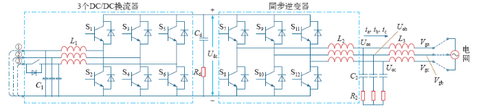
图1
光储一体虚拟同步发电机拓扑结构
Fig.1
Topology of VSG integrated with photovoltaic and battery
本结构中,一个三相全桥模块作为并网同步逆变器,将直流侧微源提供的直流电变换成三相交流电,经LCL型滤波器并入电网。
另一个三相全桥模块分解为3个DC/DC变换器,分别进行控制。每个Buck/Boost变换器均可以实现光伏或者储能的接入,将光伏侧/储能侧直流电压升压为并网同步逆变器所需的直流电压。
2.2 工作原理
本文设计的光储一体虚拟同步发电机直流源设计为2路光伏、1路储能,分别接入图1拓扑图中①~③接入点。
同步逆变器实现虚拟同步发电机控制,表现为受控交流电压源特性。
所配置的一路储能作为虚拟同步发电机的惯量单元,通过充放电能来模拟同步发电机转子存储或释放的动能。储能用DC/DC变换器采用电压-电流双环控制实现直流稳压控制。
光伏用DC/DC变换器工作在最大功率点跟踪MPPT(maximum power point tracking)模式,实现光伏最大功率输出。
3 建模与参数设计
光储一体虚拟同步发电机具备有功–频率、无功–电压两个本质控制功能,体现惯量、阻尼两个标志性特性。
3.1 有功–频率控制
有功–频率控制环源自同步发电机一次调频与惯性特性。通过调节虚拟机械转矩Tm实现同步逆变器有功指令Pset的调节;通过调频控制器实现对电网频率偏差的响应。其中,Tm由机械转矩指令T0和频率偏差反馈指令ΔT两部分组成,可以表示为
式中,ω为虚拟同步发电机实际角频率;ωn为公共母线角频率;ωref为电网基准频率;kf为调频系数。
引入同步发电机转子运动方程,得到有功–频率控制器如式(3)所示,控制框图如图2所示。
图2
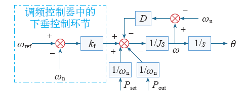
式中,Pout为实际输出有功功率;θ为实际电角度;D为阻尼系数;J为转动惯量。
在稳态时,ω≈ωref,根据控制理论与数学原理,调频系数kf和阻尼系数D归一,以有功环下垂系数Dp表示,得到有功–频率控制器为
3.2 无功–电压控制
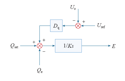
无功–电压控制环源自同步发电机一次调压与励磁特性,通过调节虚拟同步发电机的虚拟电势E来调节虚拟同步发电机交流侧电压和无功功率。无功–电压控制器如式(5)所示,控制框图如图3所示。
式中,Qe为实际输出的无功功率;Qset为设定的无功功率给定值;Dq为无功–电压下垂系数;Uref、Uo为同步逆变器机端电压有效值的指令值与实际输出值;K为励磁惯性系数。
图3
3.3 虚拟同步机小信号建模
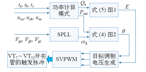
图4为虚拟同步发电机整体控制框图,首先根据采集的电压电流信号得到实际输出的有功功率、无功功率,同时采集的电网电压经SPLL得到电网角速度,再经过有功–频率控制、无功–电压控制、目标调制电压生成及SVPWM调制后得到逆变器开关管的触发脉冲,控制逆变器最终实现虚拟同步发电机控制目标。
同步逆变器进入稳态工作时,其输出的有功功率和无功功率为
图4
其中,Xs为逆变器输出阻抗与线路阻抗之和;Ug为电网三相相电压有效值;δ为VSG桥臂中点电压与电网电压之间的角度差,也称为功角。
由图5a可得虚拟同步发电机有功环的开环传递函数OP(s)和闭环传递函数CP(s)分别如式(8)和式(9)所示。
图5
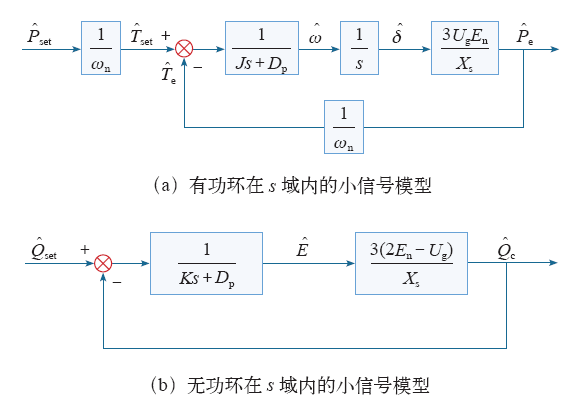
由图5b可得虚拟同步发电机无功环的开环传递函数OQ(s)和闭环传递函数CQ(s)分别如式(10)和式(11)所示。
3.4 参数设计
从上述建模分析可知,虚拟同步发电机关键控制参数有:有功环下垂系数Dp,无功环下垂系数Dq;有功环惯性系数J,无功环惯性系数K。
标准EN 50438规定逆变器接入电网连续运行电网条件为:电网电压频率在49~51Hz,电网电压幅值在90%~110%额定电压幅值。根据该标准的要求,Dp和Dq的最大值设计为:电网电压频率变化1Hz,虚拟同步发电机输出有功功率变化100%;电网电压幅值变化10%,虚拟同步发电机输出无功功率变化100%。如果以10kW虚拟同步发电机,接入三相电压为380V电网情况为例分析,那么有:Dp≤5,Dq≤321。
表1 虚拟同步机主电路参数
Tab.1
| 参 数 | 取 值 | 参 数 | 取 值 |
|---|---|---|---|
| 额定容量/kV·A | 10 | 滤波电感L2/mH | 3 |
| 直流电压/V | 700 | 网侧电感L3/mH | 1 |
| 直流侧电容/μF | 1 000 | 滤波电容/μF | 10 |
| 电网相电压/V | 220 | — | — |
表2 虚拟同步机控制参数取值范围
Tab.2
| 参 数 | 有功环 | 无功环 | ||
|---|---|---|---|---|
| Dp | J | Dq | K | |
| 取值范围 | 0~5 | 0~0.1 | 0~321 | 0~8 |
4 参数变化对虚拟同步机性能的影响
4.1 Dp、J的变化对有功环性能的影响
Xs为逆变器输出阻抗与线路阻抗之和,通常线路电感值远小于网侧电感L2,可忽略,因此有Xs = ωn(L2 + L3)。将表1所示参数代入式(8)和式(9),可得有功环的闭环传递函数为
图6
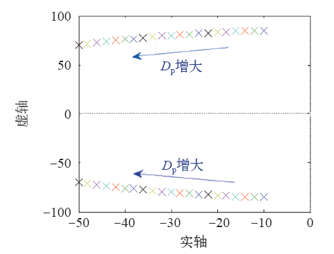
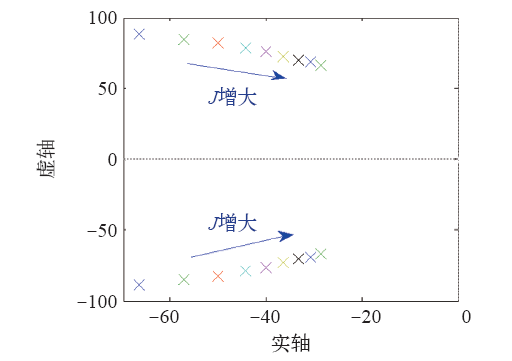
图7所示为有功环惯性系数J变化时的闭环极点分布图。J变化时,有功环闭环极点均为共轭复根,所以为欠阻尼系统。随着J的增大,有功环的闭环极点靠近虚轴,所以稳定裕度减小;在动态性能方面,随着J的增大,有功环的闭环极点实部绝对值减小,虚部绝对值减小,阻尼比减小,所以有功环超调量增大,上升时间增大,调节时间增大,振荡频率减小。J的增大使得有功环的响应变慢。随着J的增大,有功环的闭环极点分布越来越密集,即J的变化对有功环的影响随着J的增大而变弱。
图7
4.2 Dq、K的变化对无功环性能的影响
将表1中参数代入式(11)可得无功环的闭环传递函数为
图8为无功环在参数K一定、Dq变化时的闭环极点分布图。随着Dq的增大,无功环的闭环极点逐渐远离虚轴,动态性能方面,随着Dq的增大,无功环的闭环极点绝对值增大,所以无功环的响应变快,响应时间变短。随着Dq的增大,无功环的闭环极点均匀分布,所以Dq的变化对无功环的影响是持续的。
图8
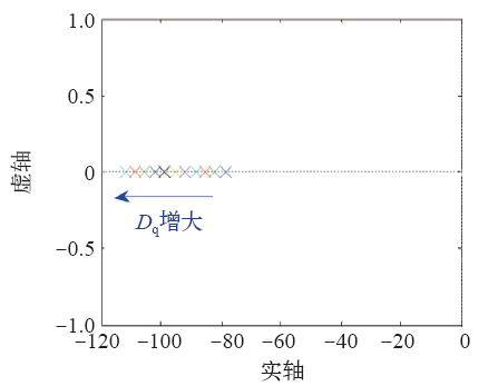
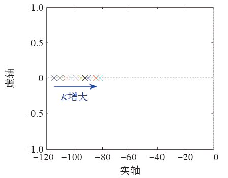
图9为无功环在参数Dq一定、K变化时的闭环极点分布图。随着K的增大,无功环的闭环极点逐渐靠近虚轴,动态性能方面,随着K的增大,无功环的闭环极点绝对值减小,所以无功环的响应变慢,响应时间变长。随着K的增大,无功环的闭环极点分布越来越密集,所以K的变化对无功环的影响随着K的增大逐渐变弱。
图9
5 仿真与实验验证
为验证光储一体虚拟同步发电机拓扑结构、控制算法和参数分析的有效性,在PSCAD/EMTDC中搭建了30kW光储一体虚拟同步发电机模型。仿真参数与研制的样机参数一致,见表3。
表3 光储一体虚拟同步发电机参数
Tab.3
| 技术参数 | 技术指标 |
|---|---|
| 直流最大输入电压/V | 1 000 |
| 直流电压范围/V | 200~1 000 |
| 直流最大输入功率/kW | 37.5 |
| 直流最大输入电流/A | 34 |
| 交流额定工作电压 | 380V,三相三线 |
| 交流电压范围/V | 300~400 |
| 交流额定输出电流/A | 45 |
| 储能配置 | 10kW、0.5h |
| 直流滤波电感L1 /mH | 1 |
| 直流侧电容C1 /μF | 100 |
| 交流侧电感L2 /mH | 1.5 |
| 直流侧电容C2 /μF | 10 |
| 交流侧电感L3 /mH | 0.1 |
| 有功环下垂系数Dp | 5 |
| 无功环下垂系数Dq | 1 |
| 有功环惯性系数J | 0.1 |
| 无功环惯性系数K | 7 |
5.1 惯量特性验证
图10
图11
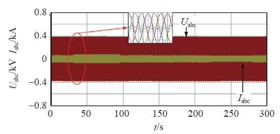
图12
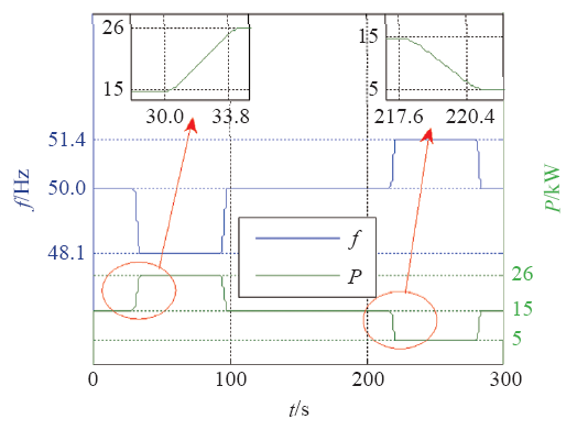
5.2 有功–频率控制验证
图13
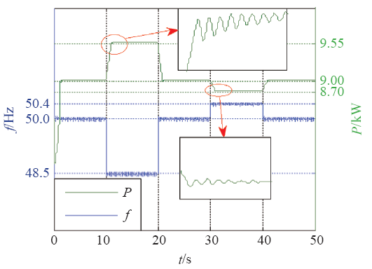
图14
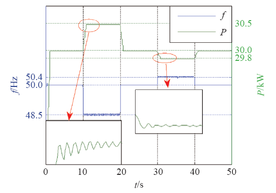
表4 系统性能指标
Tab.4
| f/Hz | 响应时间tr /s | 调节时间ts /s | 误差/kW | |
|---|---|---|---|---|
| 轻载 | 48.5 | 0.50 | 1.0 | 0.55 |
| 50.4 | 0.25 | 1.0 | 0.30 | |
| 重载 | 48.5 | 0.50 | 0.9 | 0.50 |
| 50.4 | 0.20 | 1.0 | 0.20 |
从表4可知,轻载或重载时,当电网频率发生阶跃降低或阶跃升高时,系统有功功率均能迅速响应,并快速过渡到稳态。最大稳态控制误差不大于额定功率的1.83%,响应时间不大于500ms,调节时间不大于1s。
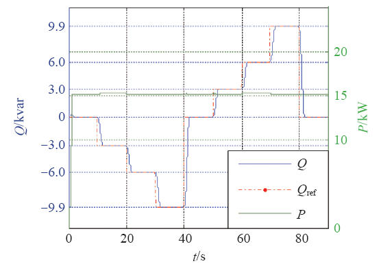
5.3 无功功率控制验证
在额定电压条件下,设置光储一体虚拟同步发电机从无功功率为零开始,以10%额定功率为变化步长运行60s并逐步降低至最小无功输出值(-30%的额定有功),运行60s后,无功功率回到零,以10%额定功率为变化步长运行60s并逐步升高至最大无功输出值(-30%的额定有功)。
无功功率响应波形如图15所示,无论无功功率给定值是正阶跃还是负阶跃,输出值均能跟随给定值,响应时间不大于1s,几乎没有无功控制误差。
图15
5.4 实验验证
设计了光储一体虚拟同步发电机试验平台,采用艾美泰克RS-270型交流可调电源作为模拟电网,容量为270kW;采用日本拓普康(Topcon)的直流模拟电源TC.GSS.32.500.400.S.HMI模拟光伏列阵,其输出功率在整个测试期间稳定在规定的功率等级,偏差±1%;采用10kW、0.5h的锂电池作为储能单元。
图16为30kW光储一体虚拟同步发电机有功–频率控制波形。三相正弦波形为输出电流波形,锯齿状波形为电池电流波形。电网频率由50Hz阶跃为49.9Hz,频率变化前设备输出有功功率7kW,频率变化后电池放电,设备输出电流增大,有功功率增加量与理论计算值相差100W,控制误差小于1%。
图16

图17为30kW光储一体虚拟同步发电机惯量特性试验波形。三相正弦波形为输出电流波形,锯齿状波形为电池电流波形。电网频率由50Hz按照1Hz/s变为48.1Hz,电池放电,有功功率增大,快速响应电网频率变化。
图17
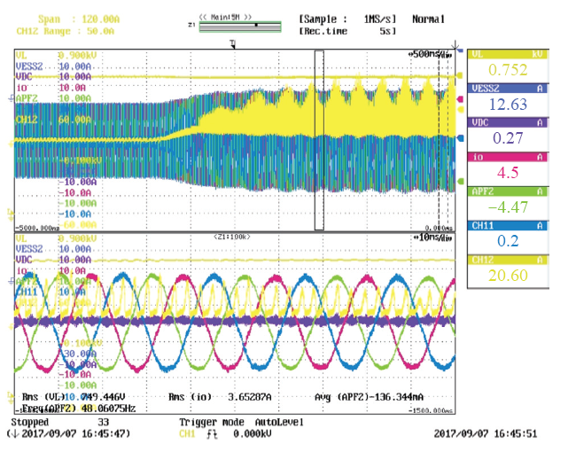
图18为30kW光储一体虚拟同步发电机无功控制试验中三相电流波形。有功功率输出8kW,无功功率设置值为5kvar,无功功率实测值为4.95kvar,无功功率控制误差小于0.5%。
图18

6 结论
本文以光储一体虚拟同步发电机为分析原型,给出虚拟同步发电机控制策略以及小信号模型,并分析了关键参数对虚拟同步发电机性能的影响。最后,基于30kW光储一体虚拟同步发电机样机,利用PSCAD/EMTDC仿真和硬件试验平台验证了控制策略、参数设计的有效性、可行性。
(1)惯量特性方面,有功环惯量系数J的增大会使得有功环响应变慢,为有功环注入一定的“惯量”,但同时会使得有功环的超调量增大,稳定裕度减小,K的增大同样可为无功环注入一定的“惯量”,使得无功环的响应变慢。
(2)一次调频特性方面,有功环下垂系数Dp的增加会增大有功环的稳定裕度,减小超调量,增大上升时间,使有功环响应的振荡减弱。
(3)无功功率控制特性方面,无功环下垂系数Dq的增大使得无功环的响应变快,响应时间变短。
参考文献
Virtual synchronous generators
[C].
虚拟同步发电机技术及展望
[J].
Review and prospect of virtual synchronous generator technologies
[J].
Reactive power control for load sharing with virtual synchronous generator control
[C].
Virtual sysnchronous machine
[C].
De Haan S W H. Virtual synchronous machines (VSG’s) for frequency stabilisation in future grids with a significant share of decentralized generation
[C].
Synchronverters: inverters that mimic syschronous generators
[J].
DOI:10.1109/TIE.2010.2048839
URL

In this paper, the idea of operating an inverter to mimic a synchronous generator (SG) is motivated and developed. We call the inverters that are operated in this way synchronverters. Using synchronverters, the well-established theory/algorithms used to control SGs can still be used in power systems where a significant proportion of the generating capacity is inverter-based. We describe the dynamics, implementation, and operation of synchronverters. The real and reactive power delivered by synchronverters connected in parallel and operated as generators can be automatically shared using the well-known frequency- and voltage-drooping mechanisms. Synchronverters can be easily operated also in island mode, and hence, they provide an ideal solution for microgrids or smart grids. Both simulation and experimental results are given to verify the idea.
Self-synchronized synchronverters: inverters without a dedicated synchronization unit
[J].
虚拟同步发电机及其在微电网中的应用
[J].
DOI:10.13334/j.0258-8013.pcsee.2014.16.009
URL
针对分布式电源并网逆变器的虚拟同步发电机控制策略及其在微电网中的应用进行研究。建立并网逆变器用虚拟同步发电机控制方案的数学模型,研究基于虚拟转矩和虚拟励磁的并网有功、无功调节方案,定量分析系统模型参数摄动对并网功率跟踪的影响,详细分析惯性和阻尼参数的整定方法,提出一种基于锁相环的虚拟同步发电机离/并网无缝切换控制策略,可模拟同步发电机的准同期并列装置。最后,针对一个典型微电网系统,利用PSCAD/EMTDC的仿真结果和一台50 kVA样机的实验结果验证所提控制策略的正确性和有效性。结果表明,所提的并网功率调节控制策略具有较好的有功、无功跟踪性能;同时,还能很好地为系统提供惯性和阻尼,提高系统稳定性,此外,还能满足微电网不同运行模式之间的无缝切换。
Virtual syschronous generator and its applications in micro-grid
[J].
DOI:10.13334/j.0258-8013.pcsee.2014.16.009
URL
针对分布式电源并网逆变器的虚拟同步发电机控制策略及其在微电网中的应用进行研究。建立并网逆变器用虚拟同步发电机控制方案的数学模型,研究基于虚拟转矩和虚拟励磁的并网有功、无功调节方案,定量分析系统模型参数摄动对并网功率跟踪的影响,详细分析惯性和阻尼参数的整定方法,提出一种基于锁相环的虚拟同步发电机离/并网无缝切换控制策略,可模拟同步发电机的准同期并列装置。最后,针对一个典型微电网系统,利用PSCAD/EMTDC的仿真结果和一台50 kVA样机的实验结果验证所提控制策略的正确性和有效性。结果表明,所提的并网功率调节控制策略具有较好的有功、无功跟踪性能;同时,还能很好地为系统提供惯性和阻尼,提高系统稳定性,此外,还能满足微电网不同运行模式之间的无缝切换。
等基于虚拟同步发电机的分布式逆变电源控制策略及参数分析
[J].To improve the contribution of distributed inverter based on power electronic interface to the required inertia of power system for stability,a novel overall control strategy based on virtual synchronous generator (VSG) is designed. The outside control of distributed inverter is constructed by using synchronous generator’s rotor motion equation,primary frequency regulation feature and the delay characteristic of reactive power regulation. The proportional resonant controller which has better tracking performance is adopted in the bottom control. Then the small-signal models of inverter with grid-connected and autonomous working mode are established. The impact of main control parameters on system stability and dynamic response is analyzed according to the state matrix eigenvalue and sensitivity calculation. Correctness of the proposed methods is verified by Digital simulation and practical experiment. The results show that the distributed inverter can work in two modes of grid-connected and autonomous. And the change of reactive power has little influence on active power. The established small-signal model can be used for system stability analysis and related control parameters optimal design.
Control strategy and parameter analysis of distributed inverters based on VSG
[J].To improve the contribution of distributed inverter based on power electronic interface to the required inertia of power system for stability,a novel overall control strategy based on virtual synchronous generator (VSG) is designed. The outside control of distributed inverter is constructed by using synchronous generator’s rotor motion equation,primary frequency regulation feature and the delay characteristic of reactive power regulation. The proportional resonant controller which has better tracking performance is adopted in the bottom control. Then the small-signal models of inverter with grid-connected and autonomous working mode are established. The impact of main control parameters on system stability and dynamic response is analyzed according to the state matrix eigenvalue and sensitivity calculation. Correctness of the proposed methods is verified by Digital simulation and practical experiment. The results show that the distributed inverter can work in two modes of grid-connected and autonomous. And the change of reactive power has little influence on active power. The established small-signal model can be used for system stability analysis and related control parameters optimal design.
基于超前滞后环节虚拟惯性的VSG控制策略
[J].
Virtual syschronous generator control strategy based on load-lag link virtual intertia
[J].
应用于光伏微网的一种虚拟同步发电机结构及其动态性能分析
[J].
A hardware structure of virtual synchronous generator in photovoltaic microgrid and its dynamic performance anaysis
[J].
考虑源端动态特性的光伏虚拟同步机多模式运行控制
[J].
Muti-mode operation control for photovoltaic virtual syschronous genetator considering the dynamic characteristics of primary source
[J].
A new droop control method for the autonomous operation of distributed energy resource interface converters
[J].
DOI:10.1109/TPEL.2012.2205944
URL
Microgrid is widely accepted as an effective mean of integrating various distributed energy resources (DERs) through their interface converters to provide electric power of high quality and reliability. These distributed resources interface converters can operate in an autonomous fashion without any communication for enhanced system reliability and reduced complexity. Conventionally, the real power-frequency droop control and the reactive power-voltage magnitude droop are adopted as the decentralized control strategies in these DERs interface converters for the autonomous power sharing operations. However, the reactive power sharing of Q-V droop control often deteriorates due to its dependence on the line impedances. In this paper, a Q-(V) over dot droop control method with (V) over dot restoration mechanism is proposed to improve reactive power sharing. Its operation principle and control method are explained and analyzed. Simulation and experimental results are presented to validate the effectiveness of the proposed method.
Reactive power control for load sharing with virtual synchronous generator control
[C].
Online grid impedance identification for adaptive control of grid-connected inverters
不同功率等级微源逆变器并联控制新方法
[J].To improve the reliability of commutation in two stage matrix converter (TSMC),a novel carrier-based modulation scheme was proposed. In rectifier,the double modulation waves were used to extent zero current commutation time,so the problems of interruption of commutation and distortion in input current caused by narrow pulses were solved. In inverter,the 60#x000b0;clamped modulation functions were taken as modulation waves to reduce the counts of commutation by one third. In cooperating modulation,the isosceles triangular waves during two adjacent carrier periods and the trapezoidal waves in one carrier period were respectively taken as carrier waves of rectifier and inverter to keep switching states same,so that the commutation processes in a period of transition from one carrier period to another were avoided and the reliability was enhanced more. The relationship between minimum commutation time of rectifier and modulation index of inverter was also analyzed. At last,an experimental prototype was designed. Experimental results compare with two existing carrier-based modulation strategies to verify the correctness and superiority of proposed modulation strategy.
New power control strategy on paralleled micro-source inverters with different power levels
[J].To improve the reliability of commutation in two stage matrix converter (TSMC),a novel carrier-based modulation scheme was proposed. In rectifier,the double modulation waves were used to extent zero current commutation time,so the problems of interruption of commutation and distortion in input current caused by narrow pulses were solved. In inverter,the 60#x000b0;clamped modulation functions were taken as modulation waves to reduce the counts of commutation by one third. In cooperating modulation,the isosceles triangular waves during two adjacent carrier periods and the trapezoidal waves in one carrier period were respectively taken as carrier waves of rectifier and inverter to keep switching states same,so that the commutation processes in a period of transition from one carrier period to another were avoided and the reliability was enhanced more. The relationship between minimum commutation time of rectifier and modulation index of inverter was also analyzed. At last,an experimental prototype was designed. Experimental results compare with two existing carrier-based modulation strategies to verify the correctness and superiority of proposed modulation strategy.
分布式发电中的虚拟同步发电机技术
[J].
Virtual synchronous generator technology in DG
[J].
