

1 引言
图1
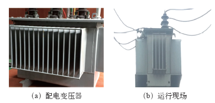
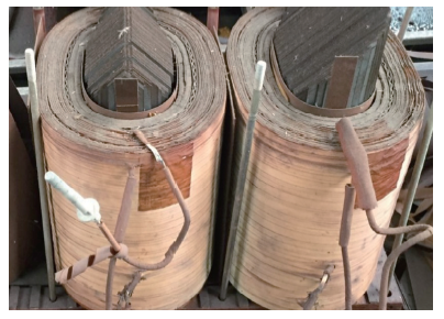
图2为现场运行配电变压器发生事故后内绝缘结构解剖情况,表明长期高过载运行已使其局部发生碳化。配电变压器内部主绝缘结构为绝缘纸板,其包覆于配电变压器绕组等结构周围,改善金属表面状态,并将大油道分割为小油道,应用薄层强化效应提升耐受电压值。实际运行中,变压器油在其内部流动,兼具绝缘和散热作用[2]。目前具备多种配电变压器运行状态的在线监测方法,如针对其不载流金属件、绕组绝缘、液体绝缘等监测其温度变化、油中气体分解产物、绝缘纸的聚合度检测等,但以上方法均需停电取样且测试时间较长[3]。鉴于此,本文提出将回复电压测试法(Return Voltage Method,RVM)应用于配电变压器油纸绝缘系统的运行状态测试。
图2
现有文献对回复电压测试法的原理、测试手段、测量结果与绝缘劣化程度之间的关系等方面进行了分析[4,5],本文针对RC集总参数电路表征回复电压测试过程中存在的理论公式推导繁琐,且集总参数不易获取的情况继续开展深入分析,在ANSYS仿真计算环境下建立配电变压器典型油纸绝缘系统模型,施加回复电压测量过程中的电压波形,分析其在关键时间点的电场分布特征。通过理论公式对多参数扩展德拜模型进行解析,并在Matlab/Simulink平台上将德拜参数模型推广至多支路集总参数电路。提出Simulink-PSO联合算法实现了德拜参数的非线性拟合,并定量分析了集总参数对极化谱的影响规律。本文分别用电场和电路方法对油纸复合绝缘回复电压进行了理论解析,提出了德拜模型集总参数反演算法,可为油浸式配电变压器绝缘状态监测提供一定的理论指导。
2 配电变压器主绝缘结构电场模拟
2.1 典型回复电压波形的特征量
图3
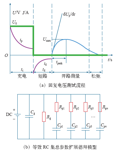
图3
回复电压测试流程及等效集总电路
Fig.3
Recovery voltage test flow and equivalent lumped circuit
另一方面,回复电压测量中的特征参量变化规律可应用等效RC集总电路模拟,如图3b所示,包括几何电容Cg、电阻Rg,表征油纸复合绝缘系统弛豫过程的支路电容Cpn、电阻Rpn。不同绝缘介质区域将有不同的极化时间常数τ=RpnCpn,极化过程主要由油纸复合绝缘介质内部空间电荷和界面电荷消散引起。对于N支路等效RC集总电路扩展德拜模型,可模拟回复电压测试流程,便于应用理论公式进行解析。
2.2 配电变压器主绝缘电场仿真模型
配电变压器绝缘介质在外施电压作用下的全电流由传导电流和极化电流两部分组成。极化电流主要是由于外施电场引起的偶极子转向极化,其为能量储存过程;当外施电场被转移,偶极子松弛恢复到原始状态,因此需讨论配电变压器在回复电压测试过程中主绝缘电场的分布情况。依据实际结构,在ANSYS仿真计算环境下建立配电变压器典型油纸绝缘系统模型如图4所示。
图4
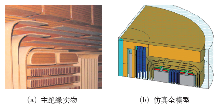
图4
变压器主绝缘实物与仿真计算模型
Fig.4
Transformer main insulation object and simulation model
图5
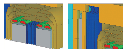
表1 电场计算中材料属性参数值
Tab.1
| 材料名称 | 相对介电常数 | 电阻率/Ω·m |
|---|---|---|
| 变压器油 | 2.2 | 3.588 6e-12 |
| 绝缘纸板 | 4.5 | 2.273 8e-15 |
| 金属部件 | 1e-10 | 1e-8 |
图6
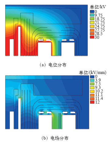
图6
配电变压器油纸绝缘系统电位和电场分布
Fig.6
Distribution of potential and E-field in oil-paper insulating system
图7为变压器主绝缘关键部位在直流和交流下电场分布情况对比,表明直流条件下场强最大值位于绝缘纸板内部,而交流条件下场强最大值位于变压器油中。回复电压测量过程中油纸绝缘结构存在暂态变化过程,下面将应用ANSYS瞬态电场分析模块进行分析。
图7
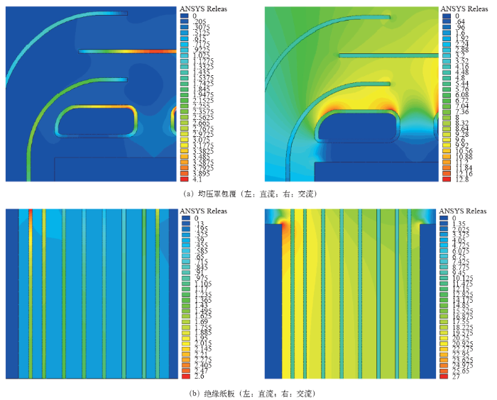
图7
关键部位直流和交流下电场分布对比
Fig.7
Comparison of E-field distribution between DC and AC
3 基于Simulink的回复电压影响因素分析
图8
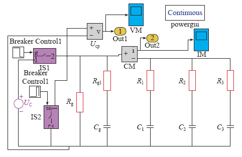
图8
基于Matlab/Simulink的回复电压仿真电路
Fig.8
Simulation circuit of recovery voltage based on Matlab/Simulink
仿真过程中电路切换过程如下:首先充电tcs,而后电路短路tds,最后电路开路。为定量分析整个过程中电路的暂态变化情况,现设定电路中各集总元件的参数值见表2,其中电阻的单位为GΩ,电容的单位为NF,仿真模拟中设置解算方法为ode23s,精度设置为1e-6,扩展德拜模型中支路数可在集总电路中任意设置,以N = 4为例进行说明。
表2 仿真电路中参数设定值
Tab.2
| 名称 | 参数 | 名称 | 参数 |
|---|---|---|---|
| Rg /GΩ | 1.75 | Cg /NF | 35.60 |
| R1 /GΩ | 5.41 | C1 /NF | 27.48 |
| R2 /GΩ | 4.36 | C2 /NF | 67.08 |
| R3 /GΩ | 13.78 | C3 /NF | 85.35 |
图9
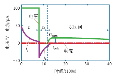
图9
油纸复合绝缘的全时域极化过程
Fig.9
Full-time domain polarization process of oil-paper composite insulation
由极化电流应用仿真可知:直流电压施加瞬间,极化电流达到最大值,而后逐渐呈指数规律下降;端口短路后其极化电流反向,呈指数规律下降至零。通过Matlab/Simulink仿真电路可有效模拟极化电压、电流在全时间域内的变化趋势。
图10
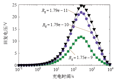
图10
极化谱与几何电阻Rg的关系
Fig.10
The relationship between polarization spectrum and geometric resistance Rg
由图10可知在几何电阻Rg增大过程中,回复电压最大值呈现增大趋势。随着充电时间tc的增大,回复电压最大值呈现先增大后减小的变化趋势,存在峰值。配电变压器温度变化较为显著时,其几何电阻Rg也将发生变化,考虑到油纸绝缘介质介电常数随温度变化较小,仿真电路中等效电容基本不发生变化。
(3)充电时间tc对回复电压波形的影响。RC集总电路确定条件下,充电时间tc对回复电压波形影响较为显著。在10-1~103s时间范围内,改变充电时间tc,得到不同的回复电压波形,如图11所示。可见在t = 0时刻,回复电压值为0V,随后回复电压陡增至最大值Urmax,而后出现下降趋势。将不同tc条件下的回复电压最大值Urmax连成曲线,可以发现,随着tc增加,Urmax出现了先增大后减小的趋势,且峰值电压出现的时间tpeak逐渐增大。仿真电路模拟结果表明,实际回复电压测量过程中为获得较为明显的电压波形,可适当调节充电时间tc使Urmax达到最大。
图11
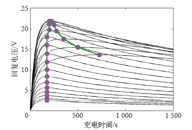
图11
充电时间tc与回复电压波形的关系
Fig.11
The relationship between charging time tc and recovery voltage waveform
对于不同型号、不同电压等级的配电变压器,其内部油纸绝缘结构存在较大差异,回复电压测量波形基本一致,均可应用基于Matlab/Simulink扩展德拜模型进行仿真模拟,以下讨论应用粒子群算法对德拜模型集总参数进行反演。
4 配电变压器扩展德拜模型的参数反演
4.1 Simulink-PSO联合算法流程
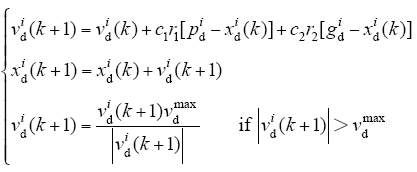
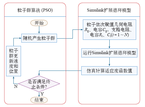
式(1)中,c1和c2为两个正常数,称为学习因子;r1和r2为[0,1]区间内的随机数;vdmax为粒子在d坐标方向上的速度限值。根据集总参数扩展德拜模型的拓扑结构可知,其反演变量包括几何电阻Rg和几何电容Cg,支路电阻、电容Ri、Ci(i = 1~N)。Simulink-PSO联合算法反演扩展德拜模型的流程如图12所示[17,18]。首先在Matlab/Simulink平台将待反演参数设置为变量,初始化粒子群,随机产生所有粒子的位置和速度,并确定粒子的Pt和Gt。对每个粒子将其适应度值与该粒子所经过的最优位置Pt和Gt的适应度值进行比较,若较好则将其作为当前的Pt和Gt,并按式(1)更新粒子速度和位置,适应度值通过运行图8所示仿真电路获取。
图12
扩展德拜模型支路数N为任意值时均存在解析解,但推导过程随N值增大愈加繁琐,以下对N = 1的情况进行全解析分析,从理论上对回复电压成因进行分析,同时验证Simulink-PSO联合算法反演多支路扩展德拜模型的有效性和准确性。
4.2 扩展德拜模型全解析理论分析
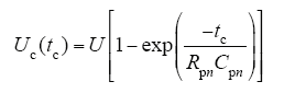
首先以N = 1扩展德拜模型为例进行全解析理论分析,从直流电压施加瞬间至tc时间范围内,第n个电容Cpn上的电压变化过程为
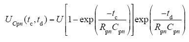
对配电变压器绝缘系统施加零电压,并进行短路处理,电容电压UCpn为
根据基尔霍夫定律可得
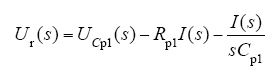
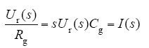
式中,I(s)为中间变量。联立式(4)和式(5)消去该变量,则回复电压和极化电容Cp1上的电压比值为
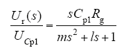
且
m = RgCgCp1Rp1l = RgCg + Rp1Cp1 + Cp1Rg
k = τg1/(τgτ1)
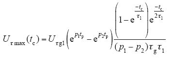
电路参数已知条件下,假设绝缘系统充电时间为tc,对上式进行拉普拉斯逆变换,得到回复电压时域表达式为
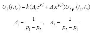
对于单一极化支路扩展德拜模型,存在四个未知量——Rg、Cg、Rp1、Cp1。可由回复电压测试曲线得到的参数有Utmax、tp,从而反推德拜模型未知量。令Rp1Cp1 = τ1,RgCg = τg,RgCp1 = τg1,德拜模型电路传递函数的极点可由特征方程中的时间常数确定,即
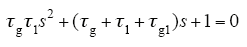
解上述方程,得到传递函数极点为
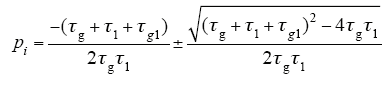
式(9)表明传递函数所有极点均为负值,因此时域曲线最终将呈现衰减趋势,且其峰值时间为 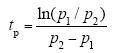
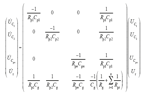
本文在Matlab中实现矩阵状态方程求解,同时在Matlab/Simulink平台上建立不同N值扩展德拜模型,对比两者模拟回复电压曲线如图13所示。其中扩展德拜模型中电容Cpn初值可通过式(3)计算,回复电压Ur初始值为零。
图13
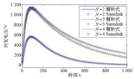
图13
解析式与Simulink模拟结果对比
Fig.13
Comparison between analytical formula and Simulink simulation results
图13表明N = 2,3,4时应用解析式与Matlab/Simulink均能模拟得到回复电压典型曲线,从初始值零逐渐增大至峰值,而后逐渐下降,解析式与Matlab/Simulink模拟计算值基本吻合,证明对于高阶德拜等效模型Matlab/Simulink计算平台可避免繁琐的公式推导,且具有较高计算精度,下面将应用Simulink-PSO联合算法反演多支路扩展德拜模型参数。
4.3 PSO算法反演德拜等效模型参数
应用Simulink-PSO联合算法反演德拜等效模型参数(N = 2),其中待反演参数包括Rg、Cg、Rp1、Cp1。设定回复电压曲线Ur已知,特征参数包括Utmax、tp、dUr/dt(t = 0) = K,若保证以上三个特征参数与已知曲线一致,则可较精确反演德拜模型参数,其适应值函数设定为
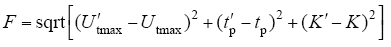
式中,U′tmax、tp′、K′为Matlab/Simulink平台模拟计算结果。Simulink-PSO联合算法运行中收敛曲线如图14所示,可见在200次迭代过程中适应度函数值逐渐下降接近于零,表明U′tmax、tp′、K′与设定值基本一致。
图14
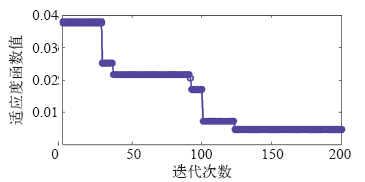
图15
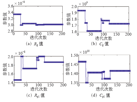
图16
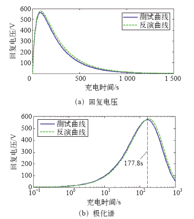
从图16可以看出,回复电压和极化谱测试曲线、反演曲线基本保持一致,说明Simulink-PSO联合算法能根据回复电压测试结果有效反演扩展德拜电路模型的集总参数。
5 配电变压器回复电压的瞬态电场分析
设定配电变压器回复电压测量过程中施加直流电压为10 000V,tc为200s,td为tc/2,应用ANSYS多物理场仿真计算软件分析配变油纸绝缘系统电位、电场的瞬态变化过程。选用瞬态分析模块,施加电压波形与回复电压施加波形一致,模拟计算时间步长设定为10s,计算时间设定为1 200s。图17为各关键时间点油纸绝缘等位线分布情况。
图17
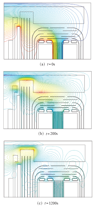
图17
关键时间点油纸绝缘系统等位线分布
Fig.17
Distribution of equipotential lines in oil-paper insulation system at critical time point
图17表明回复测试电压施加瞬间t = 0s时刻,等位线主要集中在变压器油中,变化梯度较大,证明此刻变压器油中电场场强高于纸板;在t = 200s时刻外施电压为零,但在油纸绝缘系统中等位线继续存在,直到t = 1 200s时刻等位线越加稀疏,主要分布在绝缘纸板中,此刻绝缘纸板中场强高于变压器油中。外施电压为零后仍存在等位线分布的瞬态电场模拟结果可解释回复电压产生的原因:油纸绝缘界面处电荷消散需经过足够长时间,且油纸绝缘系统电场由外施电压和界面电荷共同决定。界面电荷密度σ、等效场强E1为
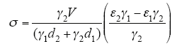
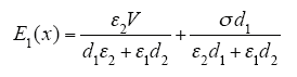
式中,V为外施电压;ε1和ε2为变压器油、绝缘纸板介电常数;d1和d2为变压器油、绝缘纸板等效厚度;γ1和γ2为变压器油、绝缘纸板电导率。式(13)、式(14)不适用于复杂拓扑结构的油纸绝缘系统,可定性说明当外施电压V = 0时,由于界面电荷密度σ ≠ 0,因此可测量得到油纸绝缘系统的回复电压变化曲线,但界面电荷密度σ将以一定时间常数τ衰减至零,回复电压波形也最终收敛至零值,与本文中德拜扩展模型计算结果一致。同时选取变压器油、绝缘纸板中关键参考点电场随时间变化曲线如图18所示,可以看出在tc时间域之前电场强度逐渐上升至最大值,随后近似阶跃下降最终指数衰减至零值。
图18
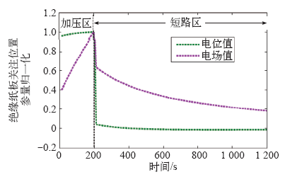
图18
关键时间点油纸绝缘系统等位线分布
Fig.18
Distribution of equipotential lines in oil-paper insulation system at critical time point
6 结束语
(1)在ANSYS仿真计算环境下建立了配电变压器典型油纸绝缘系统模型,计算结果表明交流电压下最大场强集中在变压器油中,直流电压下最大场强集中在绝缘纸板中,纸板结构对变压器油具有导向作用,同时能调制等位线分布情况。
(2)通过Matlab/Simulink仿真电路可有效模拟极化电压、电流在全时间域内的变化趋势。直流电压施加瞬间,极化电流达到最大值,而后逐渐呈指数规律下降;端口短路后电流反相,呈指数规律下降至零;回复电压全波形由零上升至Urmax,随后电压由Urmax逐渐下降为零。
(3)Matlab/Simulink仿真电路与理论计算结果一致,且Simulink-PSO联合算法反演多支路扩展德拜模型参数经约200步迭代算法趋于收敛,具有较高计算精度。针对配电变压器油纸绝缘系统瞬态电场分析可解释回复电压产生的原因,即油纸绝缘界面处电荷消散需经过足够长时间,且油纸绝缘系统电场由外施电压和界面电荷共同决定。
参考文献
高压直流输电技术现状及发展前景
[J].
To meet the demands of the construction of high-voltage direct-current (HVDC) power transmission in China and closely follow the most frontier technologies used in the manufacture of HVDC power transmission equipments, the up-to-date achievements in the development of HVDC power transmission technology are summarized. In this paper, the features of operational modes of UHVDC power transmission are presented in suammary; the develoment trend of voltage source converter (VSC) technology is described; and it is pointed out that the multi-terminal HVDC power transmission, which integrates the current natural commutation technology with flexible HVDC power transmission technology, will be the development trend of HVDC power transmission in the future. The HVDC power transmission technology utilizing capacitor commutated converters (CCC) and the common ground electrode technology as well as the technologies of converter transformers and converter valves are presented. Three technical lines for the development of optical-fiber current transformer (CT) are summarized, and the prospect of applying the full optical CT based on the principle of fiber optic interferometric sensor in HVDC power transmission is affirmed. The present situation of control and protective system utilized in HVDC power transmission summed up. Based on the operation experience, the technical and managerial dominant positions of adopting regional centralized monitoring and controlling systems (CMCS) in converter substations are expounded.
Recent advances in high-voltage direct-current power transmission and its developing potential
[J].To meet the demands of the construction of high-voltage direct-current (HVDC) power transmission in China and closely follow the most frontier technologies used in the manufacture of HVDC power transmission equipments, the up-to-date achievements in the development of HVDC power transmission technology are summarized. In this paper, the features of operational modes of UHVDC power transmission are presented in suammary; the develoment trend of voltage source converter (VSC) technology is described; and it is pointed out that the multi-terminal HVDC power transmission, which integrates the current natural commutation technology with flexible HVDC power transmission technology, will be the development trend of HVDC power transmission in the future. The HVDC power transmission technology utilizing capacitor commutated converters (CCC) and the common ground electrode technology as well as the technologies of converter transformers and converter valves are presented. Three technical lines for the development of optical-fiber current transformer (CT) are summarized, and the prospect of applying the full optical CT based on the principle of fiber optic interferometric sensor in HVDC power transmission is affirmed. The present situation of control and protective system utilized in HVDC power transmission summed up. Based on the operation experience, the technical and managerial dominant positions of adopting regional centralized monitoring and controlling systems (CMCS) in converter substations are expounded.
基于回复电压曲线的油纸绝缘状态评估
[J].
Status assessment of oil-paper insulation based on recovery voltage method
[J].
基于回复电压法的高压套管绝缘状态评估
[J].
Insulation condition evaluation of HV bushing based on RVM
[J].
变压器油纸绝缘状况的等效仿真分析
[J].
Equivalent simulation analysis on insulation state of transformer oil-paper
[J].
油纸绝缘系统回复电压函数建模及拓扑结构辨识
[J].
Return voltage function modeling and topology recognition of oil-paper insulation system
[J].
采用回复电压法分析油纸绝缘老化特征量
[J].
Analysis of oil-paper insulation aging characteristics using recovery voltage method
[J].
500kV电力变压器匝间绝缘模型线圈的电老化特性
[J].
Electrical aging characteristic of 500kV power transformer turn-to-turn insulation model coils
[J].
基于本征正交分解的换流变压器极性反转电场降阶模型
[J].
A reduced order model via proper orthogonal decomposition for polarity reverse electric fields in converter transformers
[J].
特高压换流变压器涡流损耗计算与屏蔽分析
[J].
Eddy current loss calculation and shield analysis of UHV converter transformer
[J].
基于有限元法的电力变压器金属结构件损耗分析
[J].
Power loss analysis for structural parts in transformer based on finite element method
[J].
基于扩展Debye模型仿真的回复电压特征量分析
[J].
Analysis of RVM characteristics based on the extended Debye model simulation
[J].
变压器绝缘层数和温度对回复电压影响分析
[J].
Analysis of effects of transformer insulation layers and temperature to return voltage
[J].
酸值对变压器油纸绝缘系统回复电压参数影响规律研究
[J].
Influence of acid value on recovery voltage parameters of transformer oil-paper insulation system
[J].
基于粒子群算法的变电站工频电场优化
[J].
Optimization for substation power frequency electric field distribution based on particle swarm optimization
[J].
基于量子粒子群算法的风火打捆容量及直流落点优化配置
[J].
Optimal configuration of wind&coal power capacity and DC placement based on quantum PSO algorithm
[J].
Modeling the polarization spectrum in composite oil/paper insulation systems
[J].DOI:10.1109/94.765903 URL [本文引用: 1]
