


1 引言
功率开关故障包括短路和开路故障,短路故障通常会通过快速熔断器等硬件保护措施转化为开路故障,因此,MC的故障诊断主要针对功率开关开路故障情况。目前,已有的故障诊断策略主要针对CMC拓扑,分为电流法和电压法两大类。
MC由于无中间储能环节,功率开关故障会直接影响到其输出端电压,根据MC输出电压故障特征来诊断故障开关,具有诊断速度快、准确度高和实现简单等优点[12,13,14,15,16,17]。文献[12,13,14,15]提出了基于开关误差电压的CMC故障诊断方法:根据CMC输出端相电压误差和开关信号计算9开关对应的误差电压,即开关误差电压(Switch Error Voltage,SEV),根据开关误差电压直接定位故障开关。该方法独立于CMC的调制策略、且不受负载的影响,诊断快速且准确率高,但该方法仅针对CMC拓扑。目前,针对TSMC的故障诊断方法较少,由于拓扑结构、功率开关数量以及钳位电路差异,CMC诊断方法不适用于TSMC的故障诊断。
本文针对典型的TSMC拓扑——18开关在1个功率开关或双向功率开关模块出现开路故障下的诊断策略进行研究。首先分析了CMC和TSMC的开关函数等效性,介绍了CMC基于开关误差电压的故障诊断方法,提出了TSMC开关组误差电压的概念以及基于开关组误差电压的故障开关组判断方法;接着分别针对整流级和逆变级功率开关故障,研究TSMC在故障情况下的运行模式,分析了TSMC三相输出端相电压和直流电压的故障特征,在此基础上,提出了基于开关组误差电压和直流电压故障特征的TSMC故障诊断方法。仿真研究表明:所提方法具有诊断速度快、诊断准确且算法简单易实现的特点。
2 基于开关组误差电压的TSMC故障开关组诊断方法
2.1 CMC与TSMC的开关函数等效关系
图1
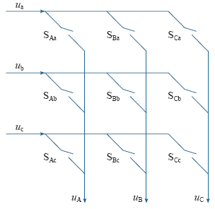
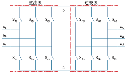
图2
CMC的输出输入相电压之间的关系为[18]
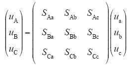
式中,uh为三相输出电压,h∈{A,B,C};uj为三相输入电压,j∈{a,b,c};Shj表示连接h相输出与j相输入的开关状态。
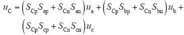
TSMC的输出输入相电压之间的关系为
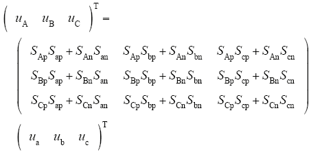
式中,Shw、Sjw表示h相输出与j相输入之间的功率开关组状态,w∈{p,n}。
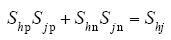
由式(1)和式(2)得CMC与TSMC开关函数的等效关系为
2.2 CMC的开关误差电压故障诊断策略
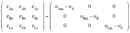
文献[13]提出了CMC基于开关误差电压的故障诊断方法,CMC的9个双向开关对应的开关误差电压为
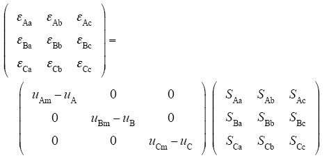
式中,uAm - uA、uBm - uB、uCm - uC为CMC三相输出端误差电压,即CMC各相输出端电压的实际检测值与计算值之间误差值,m表示检测值。εhj为根据式(4)计算得到的CMC开关误差电压值,通过这种方法,将CMC三相误差电压映射到CMC的9个双向开关上,当某一开关对应的开关误差电压大于阈值时,则该开关被诊断为故障开关[11]。
2.3 TSMC的开关组误差电压
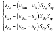
根据式(2)和式(3)得
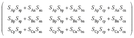
式中,uAm - uA、uBm - uB、uCm - uC为TSMC的输出端误差电压。本文将εhj定义为开关组误差电压,通过式(5)将TSMC三相输出端误差相电压映射到TSMC的9个开关组ShpSjp + ShnSjn上,当某一开关组对应的开关组误差电压大于阈值时,表明该开关组为故障开关组(即故障开关所在的开关组合)。
3 功率开关故障下TSMC运行模式及故障特征分析
3.1 逆变级开关故障下TSMC的运行模式及输出相电压故障特征分析
假设电流流入负载方向为正,反之为负,以电压源中点为参考电位,TSMC直流侧p点电压为vp,n点电压为vn,以功率开关SAp为例,在其正常和故障情况下逆变级A相电流导通路径如图3所示。
图3
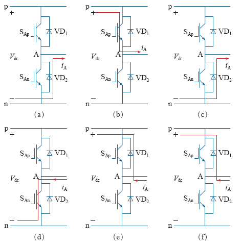
图3
逆变级A相桥臂开关在正常情况和故障情况下电流导通路径
Fig.3
Current pathes of the bridge switch of phase A in inverter stage under normal and fault conditions
表1 逆变级A相桥臂功率开关故障下TSMC输出相电压特征
Tab.1
| iA | SApSBpSCp | 正常情况输出三相相电压 | SAp开路故障输出三相相电压 | 输出相电压误差 | SAn开路故障输出 三相相电压误差 | ||||||
|---|---|---|---|---|---|---|---|---|---|---|---|
| uA | uB | uC | uAm | uBm | uCm | εA | εB | εC | |||
| >0 | 000 | vn | vn | vn | vn | vn | vn | 0 | 0 | 0 | 无误差 |
| 001 | vn | vn | vp | vn | vn | vp | 0 | 0 | 0 | ||
| 010 | vn | vp | vn | vn | vp | vn | 0 | 0 | 0 | ||
| 011 | vn | vp | vp | vn | vp | vp | 0 | 0 | 0 | ||
| 111 | vp | vp | vp | vn | vp | vp | vn-vp | 0 | 0 | ||
| 100 | vp | vn | vn | vn | vn | vn | vn-vp | 0 | 0 | ||
| 101 | vp | vn | vp | vn | vn | vp | vn-vp | 0 | 0 | ||
| 110 | vp | vp | vn | vn | vp | vn | vn-vp | 0 | 0 | ||
| iA | SApSBpSCp | 正常情况输出三相相电压 | SAn开路故障输出三相相电压 | 输出相电压误差 | SAp开路故障输出 三相相电压误差 | ||||||
| uA | uB | uC | uAm | uBm | uCm | εA | εB | εC | |||
| <0 | 000 | vn | vn | vn | vp | vn | vn | vp-vn | 0 | 0 | 无误差 |
| 001 | vn | vn | vp | vp | vn | vp | vp-vn | 0 | 0 | ||
| 010 | vn | vp | vn | vp | vp | vn | vp-vn | 0 | 0 | ||
| 011 | vn | vp | vp | vp | vp | vp | vp-vn | 0 | 0 | ||
| 111 | vp | vp | vp | vp | vp | vp | 0 | 0 | 0 | ||
| 100 | vp | vn | vn | vp | vn | vn | 0 | 0 | 0 | ||
| 101 | vp | vn | vp | vp | vn | vp | 0 | 0 | 0 | ||
| 110 | vp | vp | vn | vp | vp | vn | 0 | 0 | 0 | ||
3.2 整流级功率开关故障下TSMC运行模式及输出相电压故障特征分析
图4
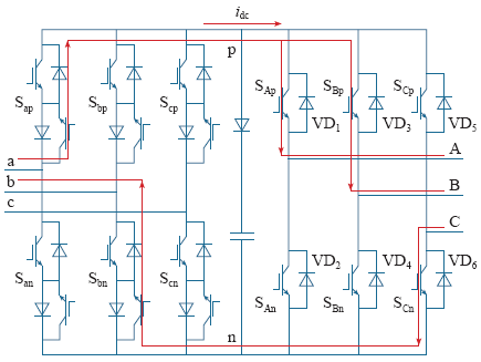
图4
idc>0整流级正常工作时电流流经途径
Fig.4
idc>0, current path when rectifier stage under normal condition
图5
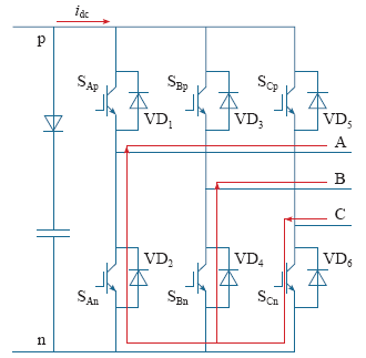
图5
idc>0整流级故障时电流流经途径
Fig.5
idc>0, current path when rectifier stage under fault condition
图6
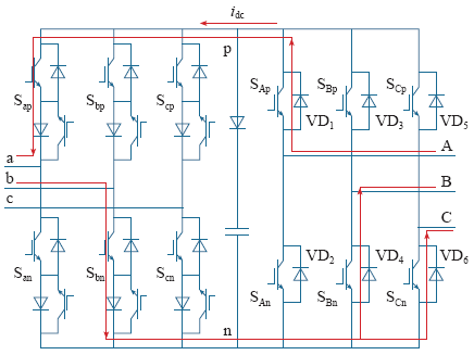
图6
idc<0整流级正常工作时电流流经途径
Fig.6
idc<0, current path when rectifier stage under normal condition
图7
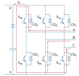
图7
idc<0整流级故障时电流流经途径
Fig.7
idc<0, current path when rectifier stage under fault condition
表2 整流级上桥臂开关故障时逆变级输出相电压故障特征
Tab.2
| idc | SApSBpSCp | 正常情况输出三相相电压 | 整流级故障输出三相相电压 | 输出相电压误差 | ||||||
|---|---|---|---|---|---|---|---|---|---|---|
| uA | uB | uC | uAm | uBm | uCm | εA | εB | εC | ||
| >0 | 000 | vn | vn | vn | vn | vn | vn | 0 | 0 | 0 |
| 001 | vn | vn | vp | vn | vn | vn | 0 | 0 | vn-vp | |
| 010 | vn | vp | vn | vn | vn | vn | 0 | vn-vp | 0 | |
| 011 | vn | vp | vp | vn | vn | vn | 0 | vn-vp | vn-vp | |
| 111 | vp | vp | vp | vn | vn | vn | vn-vp | vn-vp | vn-vp | |
| 100 | vp | vn | vn | vn | vn | vn | vn-vp | 0 | 0 | |
| 101 | vp | vn | vp | vn | vn | vn | vn-vp | 0 | vn-vp | |
| 110 | vp | vp | vn | vn | vn | vn | vn-vp | vn-vp | 0 | |
表3 整流级开关故障时逆变级输出相电压误差个数
Tab.3
| 整流级故障情况 | SApSBpSCp | 出现误差相电压个数 |
|---|---|---|
| 上桥臂故障 | 001/010/100 | 1 |
| 011/101/110 | 2 | |
| 111 | 3 | |
| 下桥臂故障 | 011/101/110 | 1 |
| 001/010/100 | 2 | |
| 000 | 3 |
由表3分析可知,整流级故障时输出端出现2相或者3相相电压误差时,故障开关处于整流级,但是只出现1相相电压误差时难以区分故障开关在整流级或逆变级。此时需根据其他故障特征信息来进行区分判断。TSMC直流侧电压为
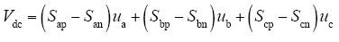
可见直流电压只受TSMC输入电压和整流级功率开关状态影响,不受逆变级功率开关状态影响,则可以根据直流电压信息来判断故障开关所在区域。
4 基于开关组误差电压的TSMC故障诊断法
由式(2)得
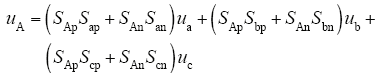
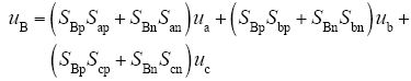
由式(7)~式(9)分析可知,TSMC输出相电压只受整流级功率开关和逆变级同相功率开关状态影响。
TSMC的故障诊断分析:
(1)设整流级开关信号为10X,逆变级开关信号为100,设置整流级Sap为故障开关(即Sap = 0),由式(7)可知此时输出端A相相电压会受影响,即uAm - uA ≠ 0,将开关信号和误差电压代入式(5)得
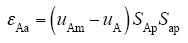
上式表明如果εAa大于设定阈值,则可判断故障开关组为SapSAp,再根据直流电压是否正常来判断故障开关所处区域。若直流电压出现误差(检测值与计算值之差),则可定位故障开关为Sap;若直流电压正常,则故障开关为SAp。
(2)设整流级开关信号为10X,逆变级开关信号为100,设置逆变级SAp为故障开关(即SAp = 0),由式(7)可知此时输出端A相相电压会受影响,即uAm - uA ≠ 0,将开关信号和误差电压代入式(5)得
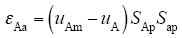
上式表明,如果εAa大于设定阈值,则可判断故障开关组为SapSAp,SAp故障对于直流电压无影响,因而根据直流电压可判断故障开关处于逆变级,结合诊断出的故障开关组,最后定位故障开关为SAp。
(3)设整流级开关信号为10X,逆变级开关信号为110,设置Sap为故障开关(即Sap= 0),由式(7)和式(8)可知此时输出端A、B两相相电压会出现误差,即uAm - uA ≠ 0,uBm - uB ≠ 0,将开关信号和误差电压代入式(5)得
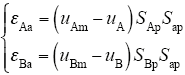
上式表明,如果εAa和εBa大于设定阈值,则可判断故障开关组为SApSap和SBpSap,且故障开关处于整流级,根据故障开关组提供的开关信号,可判断故障开关为Sap。
(4)设整流级开关信号为10X,逆变级开关信号111,设置Sap为故障开关(即Sap = 0),由式(7)、式(8)和式(9)可知此时输出端A、B、C三相相电压会出现误差,即uAm - uA ≠ 0,uBm - uB ≠ 0,uCm - uC ≠ 0,将开关信号和误差电压代入式(5)得
上式表明,如果εAa、εBa和εCa大于设定阈值,则可判断故障开关组为SApSap、SBpSap和SCpSap,且故障开关处于整流级,根据故障开关组提供的开关信号,可判断故障开关为Sap。
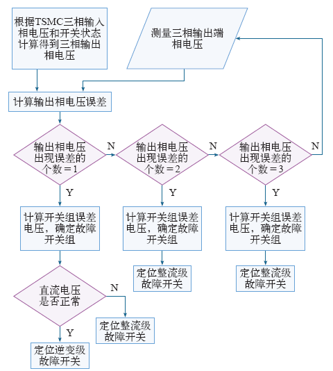
上述分析表明,整流级功率开关故障会在TSMC三相输出端产生1相、2相或3相输出相电压误差情况(与逆变级开关状态相关),逆变级开关故障只会出现1相相电压误差情况。理论分析结果与上节TSMC相应故障下运行模式分析结果一致。根据上述分析可知,若判断出TSMC有2相或者3相相电压误差,则可判断故障开关处于整流级;若判断出只有1相相电压误差,则需要借助直流电压误差来判断故障发生的区域,如果有直流电压误差,则故障开关处于整流级,如果无直流电压误差,则故障开关处于逆变级。诊断方法流程如图8所示。
图8
5 仿真结果
在Matlab/Simulink仿真环境搭建了TSMC的故障诊断系统仿真模型,对提出的故障诊断方法进行验证。仿真参数:三相对称输入电压为220V/50Hz,开关周期为0.1ms,TSMC输出频率为100Hz,采样频率为1MHz,钳位电路电容容量10μF。阻感负载参数:每相电阻值为5Ω,每相电感值为5mH。
图9
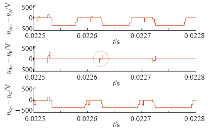
图9
Sap故障时的输出三相误差电压
Fig.9
The output three-phase error voltages when Sap failure
图10
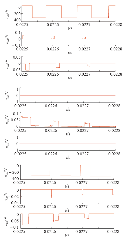
图10
Sap故障时的9个开关组误差电压
Fig.10
Nine switch group error signal voltages when Sap failure
图11
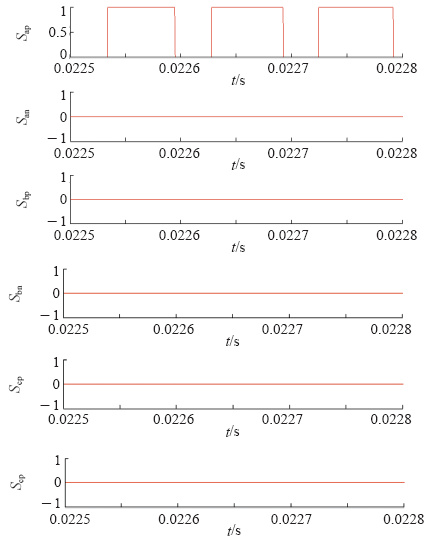
图11
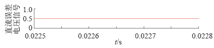
Sap故障时检测到的整流级开关故障信号
Fig.11
Detected the switch fault signal in rectifier stage when Sap failure
图12
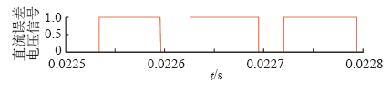
图13
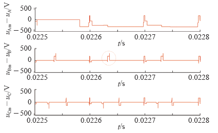
图13
SAp故障时的输出三相误差电压
Fig.13
The output three-phase error voltages when SAp failure
图14
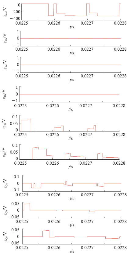
图14
SAp故障时的9个开关组误差电压
Fig.14
SAp failure,nine switch group error signal voltages
图15
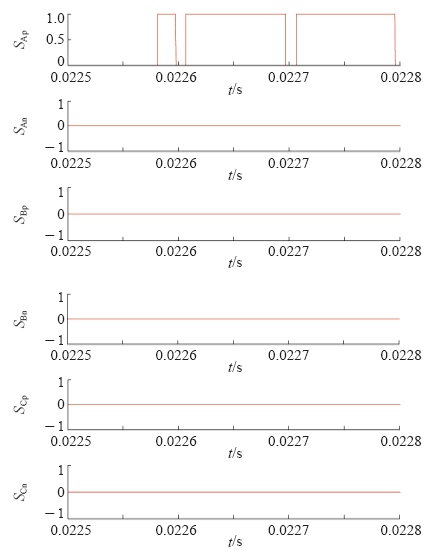
图15
SAp故障时检测到的逆变级开关故障信号
Fig.15
Detected the switch fault signal in inverter stage when SAp failure
图16
6 结论
本文分析了功率开关故障下TSMC的运行模式及其三相输出端相电压和直流电压的故障特征,提出了TSMC开关组误差电压的概念以及故障诊断方法。根据开关组误差电压来判断故障开关组,并进一步根据直流电压误差来判断故障所在区域,从而定位故障开关。所提方法具有诊断速度快,准确度高,实现简单,不受调制策略和负载影响的优点。仿真结果验证了理论分析和所提诊断方法的正确性和有效性。
参考文献
An approach to fault-tolerant three-phase matrix converter drives
[J].DOI:10.1109/TEC.2006.888018 URL [本文引用: 1]
Design of matrix converter topology and modulation algorithms with shorted and opened failure tolerance
[C].
A fault tolerant space vector modulation strategy for matrix converter
[C].
A new hardware solution for a fault tolerant matrix converter
[C].
Fault tolerant four-leg matrix converter drive topologies for aerospace applications
[C].
Four-leg-based fault tolerant matrix converter schemes based on switching function and space vector methods
[J].
DOI:10.1109/TIE.2011.2143378
URL
[本文引用: 1]

A four-leg-based fault-tolerant matrix converter topology is proposed, along with switching function and space vector approaches for modulation schemes, to improve the reliability of matrix converter drives. The four-leg-based fault-tolerant structure utilizes an additional redundant phase module. Based on the reconfigured hardware topology, fault-tolerant modulation strategies with both switching function and space vector approaches are developed to provide the matrix converter drives with continuous and disturbance-free operation. Pulsewidth-modulated algorithms with closed-form expressions, based on a switching function matrix, are presented to synthesize redefined output waveforms with reconfigured converter structures. Furthermore, a space-vector-based scheme using the indirect equivalent circuit with the fictitious dc link is also developed for the fault-tolerant topology after failures. Experimental results show the feasibility of the proposed four-leg-based fault-remedial approach, along with the developed modulation techniques.
A new fault diagnosis method and a fault-tolerant switching strategy for matrix converters operating with optimum alesina-venturini modulation
[J].
DOI:10.1109/TIE.2011.2161062
URL
[本文引用: 1]
This paper presents a new diagnostic technique for the diagnosis of open-circuit faults in matrix converters operating with an Optimum Alesina-Venturini modulation scheme. Compared to previous diagnostic techniques developed for matrix converters, the technique proposed in this paper has the major advantage of not requiring the installation of any additional sensors in the converter besides the ones already present for control purposes. Hence, it can be easily integrated into the control platform of the converter at no additional cost. In addition to the diagnostic approach, a new fault-tolerant switching strategy is also presented so that after the appearance of an open-circuit fault, the matrix converter can continue to run although with degraded performance, until a repair action can be taken. Several simulation and experimental results are presented, demonstrating the effectiveness and applicability of the developed techniques.
An on-line fault detection and a post-fault strategy to improve the reliability of matrix converters
[C].
Fault- tolerant matrix converter motor drives with fault detection of open switch faults
[J].
DOI:10.1109/TIE.2011.2162711
URL
[本文引用: 1]
This paper describes a novel fault-tolerant matrix converter motor drive system which requires an appropriate control strategy and the application of an effective fault detection technique. Two types of fault-tolerant matrix converter, a direct matrix converter and an indirect matrix converter, are proposed for a permanent magnet synchronous motor drive against open-circuit faults in safety-critical applications. A fault-tolerant control strategy is developed in order to maintain the continuous operation of the drive system with satisfactory performance. A high-speed fault detection strategy for detecting and identifying the faulty open-circuited switches located in the fault-tolerant four-phase direct matrix converter is also proposed. Simulation and experimental results are shown to demonstrate the effectiveness of the proposed fault-tolerant matrix converters and the developed fault detection strategy applied to the motor drive system under faulty operating conditions.
Improvement of matrix converter drive reliability by online fault detection and a fault-tolerant switching strategy
[J].
DOI:10.1109/TIE.2011.2151818
URL
[本文引用: 1]
The matrix converter system is becoming a very promising candidate to replace the conventional two-stage ac/dc/ac converter, but system reliability remains an open issue. The most common reliability problem is that a bidirectional switch has an open-switch fault during operation. In this paper, a matrix converter driving a speed-controlled permanent-magnet synchronous motor is examined under a single open-switch fault. First, a new fault-detection method is proposed using only the motor currents. Second, a novel fault-tolerant switching strategy is presented. By treating the matrix converter as a two-stage rectifier/inverter, existing modulation techniques for the inverter stage can be reused, whereas the rectifier stage is modified by control to counteract the fault. However, the proposed techniques require no additional hardware devices or circuit modifications to the matrix converter. Experimental results show that the proposed method can maintain the motor speed with a maximum ripple of 2%-a fivefold improvement over the uncompensated system. The proposed method therefore offers a very economical and effective solution for the matrix converter fault tolerance problem.
Open-circuit fault diagnosis for matrix converter drives and remedial operation using carrier-based modulation methods
[J].
DOI:10.1109/TIE.2013.2240639
URL
[本文引用: 2]
A novel monitoring system, designed to detect open-circuit (OC) faults that occur in the matrix converter (MC) topology, is proposed in this work. In this monitoring system, a new diagnosis method is implemented which is based on the discrete wavelet transform analysis of the measured output current waveform. In order to ensure the effectiveness of the proposed method and its resistivity to erroneous fault detections, a fuzzy expert system is used in the designed monitoring system. The main advantages of the proposed method are that the implementation cost is minimized because no extra sensors are used and that no information from the control algorithm about the modulation parameters or the applied pulse sequence is required, reducing its implementation complexity and facilitating a more modular design. Additionally, it can be easily adapted to modified matrix topologies. A simple and robust method for the localization of the open-circuited transistor(s) within the identified faulty leg is also proposed. The proposed techniques are validated by simulation and experimental tests. The remedial operation of MC drives after the occurrence of an OC fault by using a redundant leg is also studied. The use of carrier-based modulation methods for this operation is experimentally validated, and related issues are discussed.
A new method for the detection and location of faults in matrix converters
[C].
Analysis and diagnosis of open-circuit faults in matrix converters
[J].
DOI:10.1109/TIE.2010.2098356
URL
[本文引用: 3]
The monitoring of power converters is critical for obtaining systems with self-diagnostic capabilities and fault-tolerant features. This paper presents an analytical work concerning the operation of matrix converters (MCs) under the presence of open-circuit faults and discusses the applicability of a method for the diagnosis of this type of failures. The proposed method uses the absolute values of nine modulated error voltages for the continuous monitoring of the condition of the bidirectional switches of an MC. This method allows a fast detection and location of the faulty switches, independent of the modulation strategy of the converter, its voltage transfer ratio, output frequency, or type of load connected to it, both in steady-state and transient regimes. The theory, validated by simulation and experimental results, demonstrates the applicability of the proposed technique for the diagnosis of faults in MCs.
Modulated error voltages for the diagnosis of faults in matrix converters
[C].
Output error voltages—A first method to detect and locate faults in matrix converters
[C].
Fault detection and location of open-circuited switch faults in matrix converter drive systems
[C].
Fault-tolerant structure and modulation strategies with fault detection method for matrix converters
[J].DOI:10.1109/TPEL.2009.2040001 URL [本文引用: 1]
