

1 引言
耦合电感是常用的集成磁件,通过将两个以上的电感进行耦合集成,使得电感内部的电流纹波发生变化,进而改善变换器的内部性能以减小电流纹波或提升动态响应[4⇓⇓-7]。耦合电感常应用于对称的单相变换器(即Cuk、Zeta、Sepic等)、多相变换器交错并联、交错串联、三电平变换器等以及谐振变换器中[8-9]。然而,对于两电感不对称集成情况,如二次型Boost变换器,多输入、多输出变换器等,相关研究文献尚少[10]。本文从耦合电感数学模型角度出发,分析耦合电感端电压、耦合电感自感及其耦合系数对耦合电感电流纹波的影响,从而获得对具体拓扑电路中电感进行磁集成时电感端口应满足的电压条件,以及集成后减小电感电流纹波的设计准则,为变换器耦合磁集成分析与设计提供参考[11]。
2 耦合电感数学模型
图1
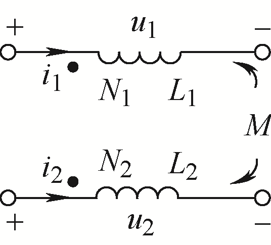
绕组两端点电压分别为
由式(1)可得
设耦合系数为k,则
3 电感电流纹波分析
3.1 影响电流纹波因素分析
由于耦合电感绕组施加不同频率电压会导致高频电感耦合低频电压,低频电感耦合高频电压,从而使高低频电感无法以正常的方式工作,因此需要
图2
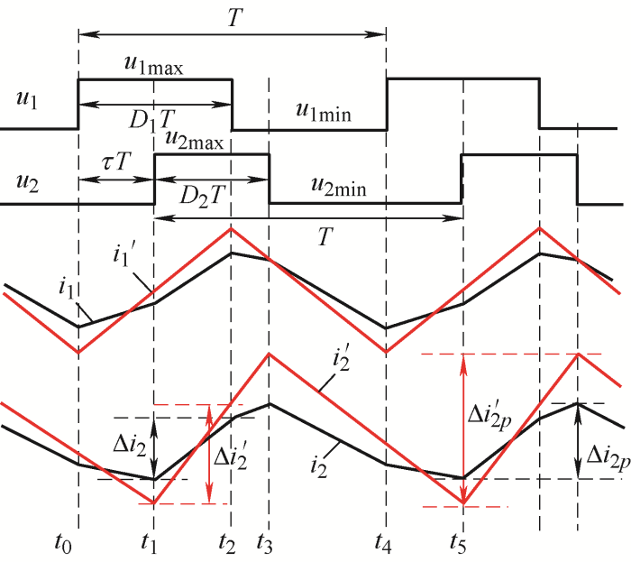
由于耦合电感结构对称,下文以电感L2纹波进行分析。非耦合时电感L2有如下表达式
电感耦合后,当绕组电压发生变化时,根据式(4)和式(5)可得
由图1可见,L1、L2的耦合方式由电流的方向确定,当利用耦合系数k的正负表示耦合方式时,式(6)可表示为
设绕组电压比
令
3.2 参数限制条件
由式(10)可得
代入互感表达式得
对于耦合电感,始终存在互感小于等于最大实际自感,即
由式(13)可知,构造新拓扑电路时,绕组电压比
由式(3)和式(4)可得
式(14)表明,
3.3
或
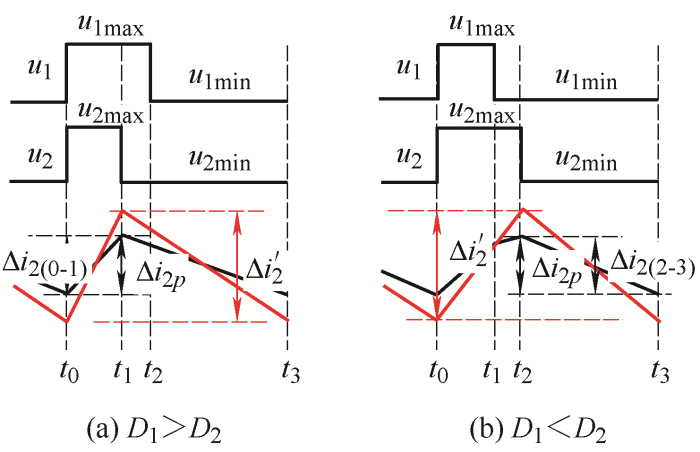
图3
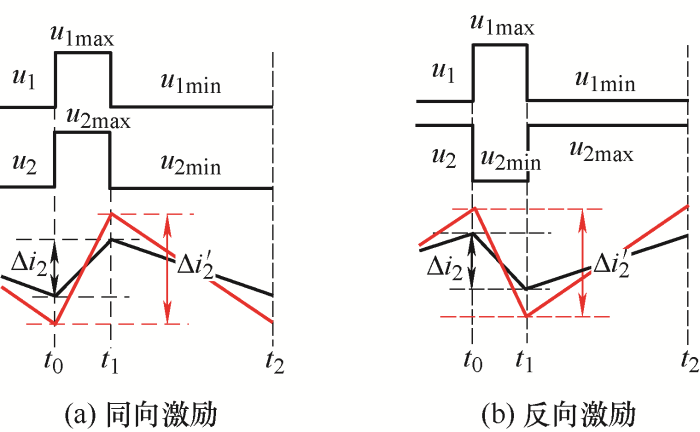
图4
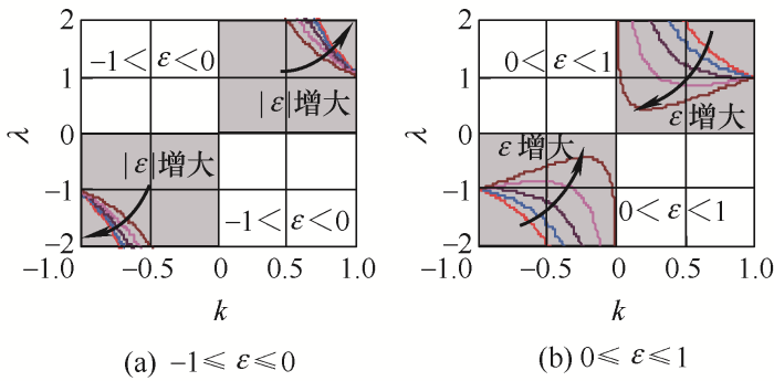
图5
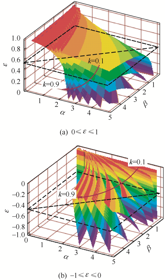
图6
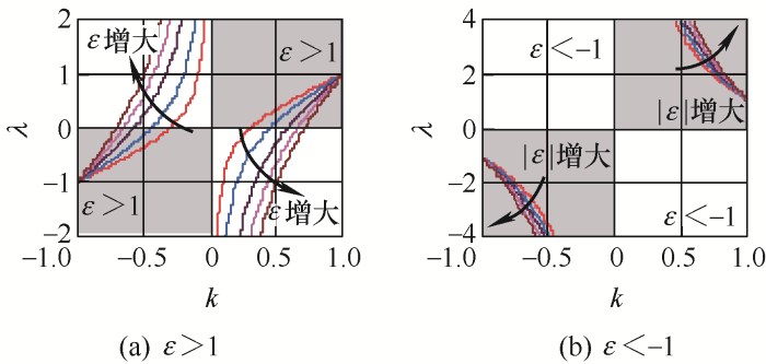
3.3.1 纹波倍数
(1) 耦合方式。由图4可知,在正向耦合
(2) 设计实现。利用式(8)得到
(3) 参考规律。
1) 如图5a所示,在耦合前后电流变化规律相同情况下,对于已经设计好的耦合电感
2) 如图5b所示,在耦合前后电流变化规律相反情况下,对于已经设计好的耦合电感
3.3.2 纹波倍数
(1) 耦合方式。
1) 实现
在正向耦合
在反向耦合
2) 实现
上述分析表明,要实现电流纹波
(2) 设计实现。利用式(8)得到
图7
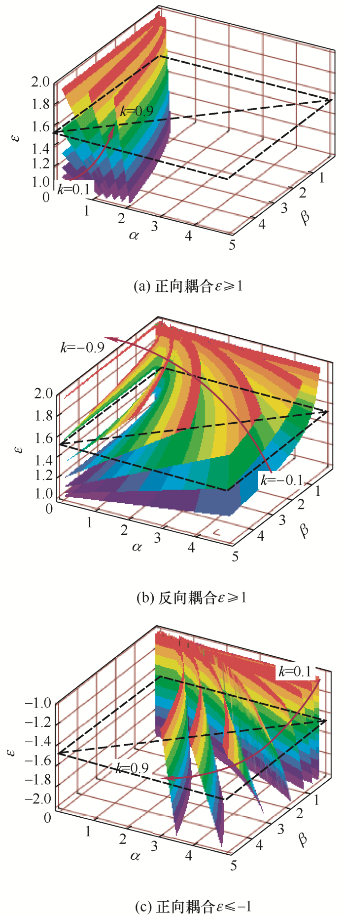
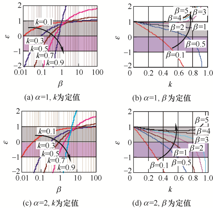
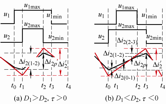
(3) 参考规律。
1) 如图7a和7b所示,在耦合前后电流变化规律相同的情况下,对于已经设计好的耦合电感
2) 如图7c所示,在耦合前后电流变化规律相反的情况下,对于已经设计好的耦合电感
图8
3.4
当绕组电压比
3.4.1
分为
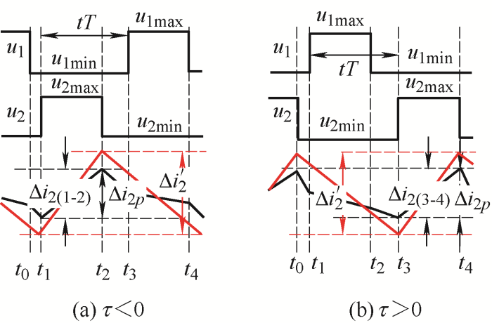
图9
此种情况耦合电感L2的电流纹波是某一时间段的电流变化量,即
3.4.2
分为
图10
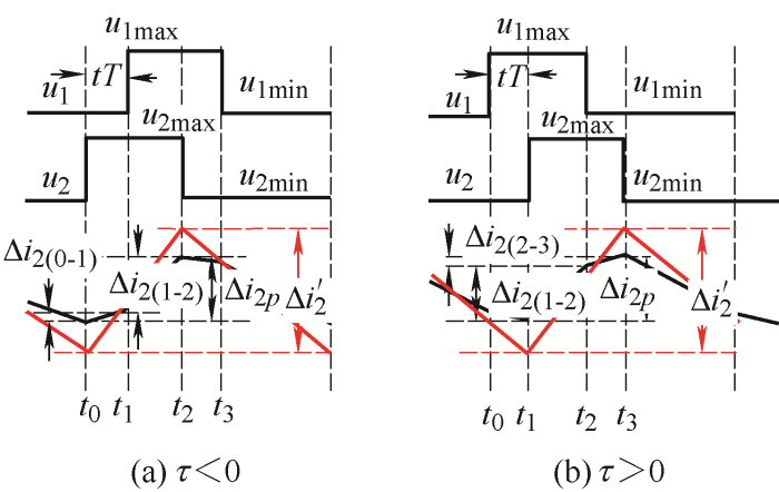
图11
1)
2)
图12
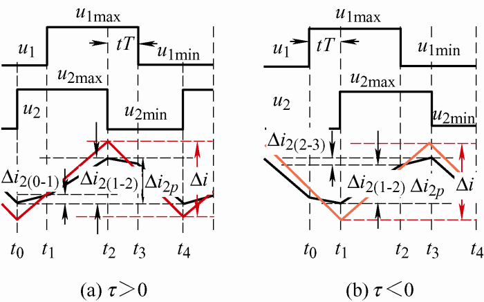
图13
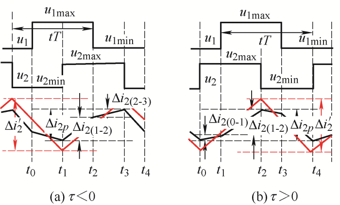
1)
2)
3.4.3
图14
绕组电压比
表1 电流纹波计算方式
| 相位与占空比条件 | 电流纹波计算方式 | ||
|---|---|---|---|
| 1 | τ=0 D1≠D2 | 某一时间段变化量 | |
| 2 | τ≠0 D1=D2 Di<0.5 | |τ|<Di | 两个时段变化量叠加值 |
| |τ|>Di | |||
| 3 | τ≠0 D1=D2 Di>0.5 | |τ|<Di | 两个时段变化量叠加值 |
| |τ|>Di | |||
| 4 | τ≠0 D1≠D2 | τ>0 | 某一时间段变化量 |
| τ<0 | 三个时段变化量叠加值 | ||
因为
电感L2电流纹波仅是某一时段的情况。
对于电流纹波为多个时段电流变化量叠加的情况,其电流纹波变化倍数
对于两个时段情况
对于三个时间段情况
式中,
3.5 电感L1电流纹波
在已知各时段电感L2电流变化量
依据第3.3节理论计算电感L1电流纹波
4 仿真验证
仿真参数设置如下:fs=100 kHz,L1=L2=100 μH,则电感自感比为
4.1
在
图15
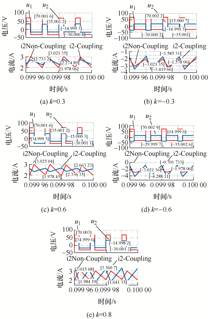
正向耦合电流纹波倍数仿真与理论计算对比如表3所示,对比结果验证了式(8)的正确性。
表3
| 耦合系数k | 占空比 | 纹波变化倍数 | 误差 | ||
|---|---|---|---|---|---|
| D1 | D2 | 理论 | 仿真 | ||
| 0.3 | 0.3 | 0.3 | 0.439 5 | 0.439 4 | -0.000 1 |
| 0.6 | 0.3 | 0.3 | 0.312 3 | 0.312 5 | 0.000 2 |
| 0.8 | 0.3 | 0.3 | 1.666 7 | 1.666 6 | -0.000 1 |
| -0.3 | 0.3 | 0.3 | 1.758 2 | 1.758 2 | 0 |
| -0.6 | 0.3 | 0.3 | 3.437 5 | 3.437 5 | 0 |
4.2
4.2.1
正向耦合与反向耦合时施加与绕组上的电压如表4所示。
表4 绕组上施加的电压 V
| 名称 | u1max | u1min | u2max | u2min | |
|---|---|---|---|---|---|
| k>0, τ=0 | D1>D2 | 60 | -40 | 35 | -15 |
| D1<D2 | 70 | -30 | 30 | -20 | |
| k<0, τ=0 | D1>D2 | 60 | -40 | 15 | -35 |
| D1<D2 | 70 | -30 | 20 | -30 | |
图16
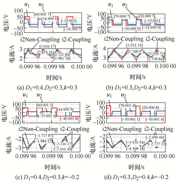
表5
| 耦合系数k | 占空比 | 纹波变化倍数 | 误差 | ||
|---|---|---|---|---|---|
| D1 | D2 | 理论 | 仿真 | ||
| 0.3 | 0.4 | 0.3 | 0.533 7 | 0.533 8 | 0.000 1 |
| 0.3 | 0.3 | 0.4 | 0.604 4 | 0.605 4 | 0.001 0 |
| -0.2 | 0.4 | 0.3 | 1.398 8 | 1.398 9 | 0.000 1 |
| -0.2 | 0.3 | 0.4 | 1.354 2 | 1.355 6 | 0.001 4 |
4.2.2
根据第3.4节分析,在
表6 绕组上施加的电压 V
| 名称 | u1max | u1min | u2max | u2min |
|---|---|---|---|---|
| k>0, τ > 0 | 70 | -30 | 35 | -15 |
| k >0, τ<0 | 70 | -30 | 35 | -15 |
| k <0, τ>0 | 70 | -30 | 35 | -15 |
| k<0, τ<0 | 70 | -30 | 35 | -15 |
图17
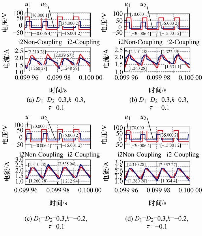
表7
| 耦合系数k | Di | τ | 纹波变化倍数 | 误差 | |
|---|---|---|---|---|---|
| 理论 | 仿真 | ||||
| 0.3 | 0.3 | 0.1 | 0.753 5 | 0.753 4 | 0.000 1 |
| 0.3 | 0.3 | -0.1 | 0.753 5 | 0.753 6 | 0.000 1 |
| -0.2 | 0.3 | 0.1 | 1.259 9 | 1.260 0 | 0.000 1 |
| -0.2 | 0.3 | -0.1 | 1.259 9 | 1.259 9 | 0 |
4.2.3
根据第3.4节分析,在
图18
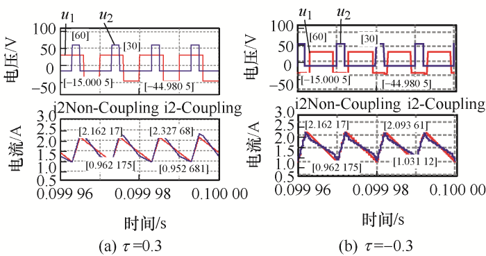
表9
| 耦合系数k | Di | τ | 纹波变化倍数 | 误差 | |
|---|---|---|---|---|---|
| 理论 | 仿真 | ||||
| -0.2 | D1=0.6, D2=0.2 | 0.3 | 1.145 8 | 1.145 8 | 0 |
| -0.2 | D1=0.6, D2=0.2 | -0.3 | 0.885 4 | 0.885 4 | 0 |
5 结论
本文对变换器中电感磁集成电流纹波变化进行研究,以两电感耦合的通用数学模型角度出发,分析了耦合电感的端电压、自感、耦合系数以及相位差对耦合电感电流纹波的影响,分析了在不同情况下,电感耦合后电流纹波变化情况并给出纹波变化规律,通过仿真验证不同情况下,电感耦合后电流纹波的变化,本文所分析的磁集成纹波设计准则可应用于各种串联、并联、组合、双输入变换器中。
参考文献
一种新型单元耦合阵列化可变耦合度集成磁件的研究及应用
[J].
Research and application of a new type of unit coupling array variable coupling integrated magnetic parts
[J].
“目”字形耦合电感器的设计及应用
[J].
Design and application of ‘mu’-shaped coupling inductor
[J].
多相交错并联磁集成双向DC/DC变换器中耦合电感的通用设计准则
[J].
General design criteria for coupled inductors in multiphase interleaved magnetic integrated bidirectional DC/DC converters
[J].
DCM模式下交错并联磁集成双向DC/DC变换器的稳态性能分析
[J].
Steady-state performance analysis of interleaved magnetic integrated bidirectional DC/DC converter in DCM mode
[J].
“E王E”形耦合电感器的设计及其在交错并联磁集成双向DC-DC变换器中的应用
[J].
Design of ‘E 王 E’-shape coupled inductors and its application in interleaving magnetic integrated bidirectional DC-DC converter
[J].
交错并联磁耦合双向DC-DC变换器非对称耦合电感的研究
[J].
Research on asymmetric coupled inductors of interleaved magnetically coupled bidirectional DC-DC converters
[J].
交错并联磁集成Buck变换器本质安全性输出纹波电压的分析
[J].
Analysis of output ripple voltage of intrinsically safe interleaved magnetic integrated Buck converter
[J].
三相交错并联磁集成Boost变换器的内部本质安全特性
[J].
Internal intrinsic safety characteristics of three-phase interleaved magnetic integrated Boost converter
[J].
三相交错并联变换器中耦合电感的对称化
[J].
Symmetry of coupled inductors in three-phase interleaved parallel converters
[J].
交错并联磁集成双向DC/DC变换器的设计准则
[J].
Design criteria of interleaved magnetic integrated bidirectional DC/DC converter
[J].
四相VRM中无直流偏磁集成磁件
[J].
Integrated magnetic components without DC bias in four-phase VRM
[J].
三相电压调整模块中“EΠ”形耦合电感的建模与设计
[J].
Modeling andesign of ‘EΠ’-shaped coupled inductors in three-phase voltage regulation module
[J].
一种具多路LED自动均流功能的反激式磁集成变换器
[J].
A flyback magnetic integrated converter with multi-channel LED automatic current sharing function
[J].
三相双降压逆变器中电感的磁集成方式比较与优化设计
[J].
Comparison and optimization of magnetic integration methods for inductors in three-phase dual-buck inverters
[J].
一种新颖的磁集成自驱动倍流整流半桥三电平直流变换器
[J].
A novel magnetically integrated self-driven current-doubler rectified half-bridge three-level DC converter
[J].
Planar-integrated magnetics (PIM) module in hybrid bidirectional DC-DC converter for fuel cell application
[J].DOI:10.1109/TPEL.2011.2129598 URL [本文引用: 1]
Analysis and design of fully integrated planar magnetics for primary-parallel isolated boost converter
[J].DOI:10.1109/TIE.2012.2186777 URL [本文引用: 1]
A self-driven current-doubler-rectifier three-level converter with integrated magnetics
[J].DOI:10.1109/TPEL.2013.2276021 URL [本文引用: 1]
CCTT-core split-winding integrated magnetic for high-power DC-DC converters
[J].DOI:10.1109/TPEL.2013.2240394 URL [本文引用: 1]
