1 引言
随着电网向特高压大电网不断发展,输电线路的安全运行涉及多项经济、技术指标。其中,采空区因地质倾斜与沉降产生的非荷载应力将极有可能导致杆塔构件破坏、断裂、变形,造成电气安全距离不够、故障跳闸、倒杆塔断线等严重事故的发生[1 ,2 ] 。
为了保证输电线路的安全稳定运行,已有研究提出多种针对防雷绝缘[3 ] 、形变倾斜[4 ] 、风偏闪络[5 ] 等的监测防治方案。如文献[6 ]研究了基于地面散射电流的分散式监测技术,但这一方案主要保障了在线监测的有效可靠,对离线监测没有突出的改进;文献[7 ]通过特征聚类实现了输电线路绝缘子的红外定位及自动辨识,但这一方案过度依赖先验参数的选取且不具有普遍适用性;文献[8 ]建立了四跨绝缘子串-导线耦合体系有限元模型以确定输电线路的风偏闪络,但拟合公式的方法计算结果较正常值小,而刚性直棒法没有考虑风速的脉动影响。
采空区的地表会发生塌陷或水平移动的地质形态改变,这一地质变化更易造成输电杆塔的倾斜与基础不均匀沉降,导致输电杆塔发生严重的电气事故。针对这一区域的输电杆塔监测,文献[9 ]提出基于扩频编码的电磁探测系统,实现采空区的有效勘探,虽然提高了探测效率,但电磁探测系统准确度的提高以强发射功率为代价,经济性差;文献[10 ]基于北斗卫星实现输电杆塔的在线监测,但这一方案不能满足离线状态下的数据分析要求;文献[11 ]通过采空区输电杆塔的承载力计算,判断倾斜位移的安全范围,这一方案虽然为安全运行提供参考依据,但不能对杆塔状态进行在线监测。
上述针对采空区输电杆塔的监测方法,均难以同时满足监测系统的经济性和实时性要求。因此提出基于磁场传感与北斗定位的采空区输电杆塔倾斜监测与预警方法,通过磁阻传感器与北斗定位等多源监测信息融合,基于双因素分级叠合法,有效构建输电杆塔的风险预警,提高了故障检测的响应速度与运维能力;通过TMR传感器得到磁通值波动情况,以及其与对应杆塔倾斜监测预警影响因子之间的关系,实现对故障程度的有效判断及预警。
2 磁场传感模型
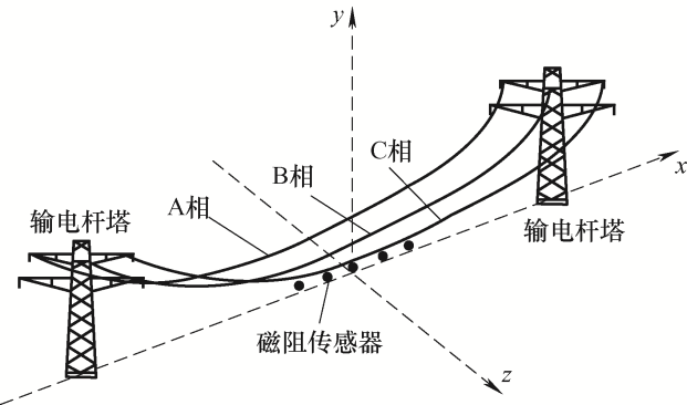
通过磁场传感的杆塔监测模式,首先需要确定架空输电线的磁场方程,如图1 所示是典型的输电塔之间的高压传输线示意图,A、B、C三相输电线周围的磁场分布受悬链线形状及其相对位置的影响。测试模型简化为三相传输线的下垂程度相同,通过叠加原理即可计算三相传输线产生的磁通密度。
图1
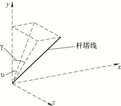
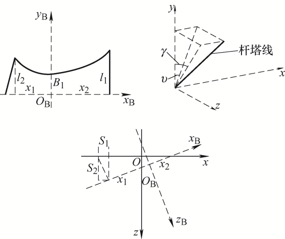
如图2 所示是输电线路的笛卡儿坐标系简化图,假设左侧杆塔倾斜,则可以确定y 轴与塔筒在x-y 平面上的投影之间的角度υ 、y 轴与塔筒在z-y 平面上的投影之间的角度γ ,通过υ 和γ 即可确定塔的倾斜程度。
图2
使用抛物线近似来描述传输线曲线,悬链线方程的近似值如文献[12 ,13 ]所述,传输线B在x -y 平面中,并且相对于y 轴对称分布
(1) $\left\{ \begin{align} & y=\upsilon {{x}^{2}}+l \\ & \upsilon =\frac{4u}{{{H}^{2}}} \\ \end{align} \right.$
式中,u 为传输线垂度;l 为距地面最低点的高度;H 为两座相邻塔的距离。应用Biot-Savart定律计算磁通密度,中距传输线B的空间中的点B 0 (x 0 ,y 0 ,z 0 )的磁场方程为
(2) $\left\{ \begin{matrix} {{B}_{0}}=\frac{{{\zeta }_{0}}}{4\text{ }\!\!\pi\!\!\text{ }}\sum\limits_{i=1}^{M}{\sum\limits_{k=-N}^{N}{\int\limits_{-H/2}^{H/2}{({{W}_{x}}{{e}_{x}}+{{W}_{y}}{{e}_{y}}+{{W}_{z}}{{e}_{z}})}}}\text{d}x \\ {{W}_{x}}=\frac{{{i}_{bi}}2\upsilon {{z}_{0}}x}{4\text{ }\!\!\pi\!\!\text{ }{{b}_{i}}}\ \ \ \ \ \ \ \ \ \ \ \ \ \ \ \ \ \ \ \ \ \ \ \ \ \ \ \ \ \ \ \ \ \ \ \ \ \ \ \\ {{W}_{y}}=-\frac{{{i}_{bi}}{{z}_{0}}}{4\text{ }\!\!\pi\!\!\text{ }{{b}_{i}}}\ \ \ \ \ \ \ \ \ \ \ \ \ \ \ \ \ \ \ \ \ \ \ \ \ \ \ \ \ \ \ \ \ \ \ \ \ \ \ \ \ \ \\ {{W}_{z}}=\frac{{{i}_{bi}}(\upsilon {{x}^{2}}+{{y}_{0}}-l)}{4\text{ }\!\!\pi\!\!\text{ }{{b}_{i}}}\ \ \ \ \ \ \ \ \ \ \ \ \ \ \ \ \ \ \ \ \ \ \ \ \ \ \ \ \ \\ {{b}_{i}}={{[{{(x-{{x}_{0}})}^{2}}+z_{0}^{2}+{{({{y}_{0}}-\upsilon {{x}^{2}}-l)}^{2}}]}^{3/2}}\ \ \ \ \ \ \\ \end{matrix} \right.$
式中,支撑结构上的单个导体的数量指定为M ;ζ 0 为自由空间的渗透性;ibi 为传输线B中的电流;e 为源到场点的单位矢量。
但是,当塔架倾斜时,确定传输线和磁场方程就变得非常困难,因为在xyz 坐标系中单个传输线的z 值并不相同,另外即使可以解得方程组的解,方程式也非常复杂。因此,使用几何变换解决这一问题,点到点的几何变换映射不会增加方程式的复杂程度。因此,转换图2 中的坐标系简化方程式,变换原始坐标系遵循以下两种原理。
(1) 保证传输线i 在xi -yi -zi 坐标系中的xi -yi 平面中(i =A、B、C)。
(2) 保证x -z 平面和xi -zi 平面在同一平面上(i =A、B、C)。
建立x B -y B -z B 坐标系,令B1 和B2 是传输线B的悬置点在倾斜之前在x -y 平面上的投影,B′是倾斜后传输线B的悬浮点在x -y 平面上的投影。得到倾斜后建立的新坐标系x B -y B -z B ,而y B 轴始终垂直于地面,令倾斜后传输线B最低点在x -z 平面上的投影点为Bxz l B 是倾斜后距地面最低点的高度,倾斜前悬挂点高度为l 1 ,倾斜后悬挂点高度为l 2 。倾斜前后传输线B的形状方程发生了变化的同时,积分范围、距地面最低点的高度和传输线B在空间 中的点B 0 (x 0 ,y 0 ,z 0 )的数值都发生了变化,如图3 所示。
图3
(3) $\left\{ \begin{align} & {{S}_{1}}={{l}_{2}}\tan \upsilon \\ & {{S}_{\text{2}}}={{l}_{2}}\tan \gamma \\ & {{l}_{1}}=\sqrt{{{l}_{2}}^{2}+{{S}_{1}}^{2}+{{S}_{2}}^{2}} \\ \end{align} \right.$
由于相对于最低点的线的形状不受塔倾角的影响,因此抛物线形状仍可以用来表示x B -y B -z B 坐标系中的传输线B,为
(4) ${{y}_{\text{B}}}^{2}={{({{\upsilon }_{\text{B}}}{{x}_{\text{B}}}^{2}\text{)}}^{\text{2}}}\text{+}{{B}_{l}}^{2}$
(5) $\left\{ \begin{align} & \upsilon {}_{\text{B}}{{x}_{1}}^{2}+{{B}_{l}}={{l}_{1}} \\ & {{\upsilon }_{\text{B}}}x{{{}_{2}}^{2}}+{{B}_{l}}={{l}_{2}} \\ & {{x}_{1}}+{{x}_{2}}=\sqrt{{{(H-{{S}_{1}})}^{2}}+{{S}_{2}}^{2}} \\ \end{align} \right.$
其中积分环节如式(2)所示。可以得到,在塔倾斜前后,传输线B的长度保持相同。
(6) $\frac{{{x}_{2}}}{{{x}_{1}}+{{x}_{2}}}=\frac{H/2-{{x}_{{{O}_{\text{B}}}}}-{{y}_{{{O}_{\text{B}}}}}}{H-{{S}_{1}}}=\frac{{{z}_{{{O}_{\text{B}}}}}}{{{S}_{2}}}$
式中,(${{x}_{{{O}_{\text{B}}}}}$,${{y}_{{{O}_{\text{B}}}}}$,${{z}_{{{O}_{\text{B}}}}}$)为xy 在xyz 坐标系中的坐标。由于x -z 平面和x B -z B 平面在同一平面上,因此${{y}_{{{O}_{\text{B}}}}}$ 为零。
一旦获得x 轴和变换后x B 轴的夹角α 以及原点O B 的坐标,就可以相应地建立x B -y B -z B 坐标系,然后计算xyz 坐标系中任意点(x ,y ,z )的x B -y B -z B 坐标系中的坐标(x B ,y B ,z B ),其中
(7) ${{x}_{\text{B}}}=\sqrt{{{(x-{{x}_{{{O}_{\text{B}}}}})}^{2}}+{{(z-{{z}_{{{O}_{\text{B}}}}})}^{2}}}\cos \beta$
(8) ${{z}_{\text{B}}}=\sqrt{{{(x-{{x}_{{{O}_{\text{B}}}}})}^{2}}+{{(z-{{z}_{{{O}_{\text{B}}}}})}^{2}}}\sin \beta$
(9) $\tan \beta =\frac{z-{{z}_{{{O}_{\text{B}}}}}}{x-{{x}_{{{O}_{\text{B}}}}}}+{{\alpha }_{\text{B}}}$
因此,在x B -y B -z B 坐标系中,点(x ,y ,z )可以用(${{x}_{{{O}_{\text{B}}}}}$,${{y}_{{{O}_{\text{B}}}}}$,${{z}_{{{O}_{\text{B}}}}}$)和α 表示,则可以利用已知参数,确定x B -y B -z B 坐标系中点的磁通密度。在xyz 坐标系中,传输线A和C产生的磁通密度的计算方法与传输线B相同,传输线A、B和C产生的总磁通密度为各项的分量加和。
3 结合北斗定位的倾斜监测与预警 方法
提出的采空区输电系统监测预警方法,基于磁阻传感器与北斗定位等多源监测信息,对输电杆塔的倾斜变化进行监测,使用双因素分级叠合的方法,量化杆塔电流和杆塔位置变化程度,实现采空区的输电杆塔倾斜监测与预警。
如图1 所示,杆塔之间设置有五个间隔为5 m的双轴磁阻传感器,传感器位于传输线B的最低点正下方。通过沿x 轴五个磁阻传感器处磁通密度的yz 分量By ,Bz ,能够估计出传输线的垂度和塔架倾斜角,通过估计参数可以精确地重建三相电流。由于y 轴与塔筒在x-y 平面上的投影之间的角度υ 、y 轴与塔筒在z-y 平面上的投影之间的角度γ 和垂度都影响了磁通密度的yz 分量,因此测量By ,Bz 即可估算υ 、γ 和传输线垂度。
磁阻传感器可以测量地面传输线下的磁通密度,进而得到磁场分布,这里使用具有低成本、低功耗和高检测精度的隧道磁阻(Tunneling magnetoresistive,TMR)[14 ] ,测得的磁场通过人工免疫系统算法的优化方法迭代更新,即可得到υ 、γ 和传输线垂度。首先根据υ 、γ 和传输线垂度求出预存储位置系数矩阵A ,然后通过最小二乘估计法计算三相电流,推导出磁通密度,最后将计算出的和测得的磁场数据之间的绝对误差与精度阈值相比较,通过AIS算法更新预存储位置系数矩阵A ,直到计算数据的和测得的磁场数据之间的绝对误差小于精度阈值,即得到准确的监测磁通值,监测磁通值的波动情况和其对应杆塔倾斜监测预警的影响因子GI 如表1 所示。
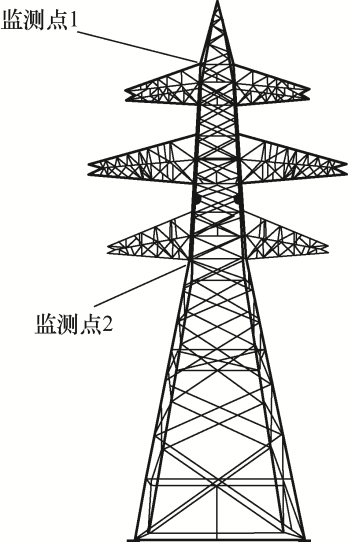
输电杆塔的北斗定位监测点如图4 所示,选取杆塔附近30 km范围的稳定基岩,作为毫米级监测要求的基准站[15 ,16 ] ,并埋设相对塔基位置固定且稳定的观测墩,以确保基准点的坐标固定不变。
图4
倾斜程度可分为塔基座位置不变和塔基座位置变动两种情况,输电杆塔由t 0 时刻的位置(x 0 ,y 0 ,z 0 )倾斜至t 时刻的位置(x' ,y' ,z' ),其中t =t 0 +Δt 。DLT/741—2019《架空输电线路运行规程》中规定杆塔变形的倾斜限值,将危险程度分为三个等级,塔基座位置不变时α ≤0.5%正常,0.5%≤α ≤1%预警,α ≥1%危险;塔基座位置变动时α ≤0.4%正常,0.4%≤α ≤0.8%预警,α ≥0.8%危险。
为准确刻画输电杆塔位置状态,将其倾斜度用状态因子GS 表示正常、预警和危险三个不同等级,如表2 所示。
使用双因素分级叠合的方法对杆塔电流和杆塔位置变化程度量化,即杆塔危险指数
$G={{G}_{I}}\centerdot {{G}_{S}}$
综上所述,根据采空区输电杆塔的运行测试模型,使用倾斜度用状态因子GS 和磁通波动影响因子GI 描述输电杆塔的运行情况,通过双因素分级叠合计算杆塔危险指数,划分输电杆塔故障预警等级,实现依赖于磁场传感和北斗定位的倾斜监测预警。
4 试验结果与分析
使用四种不同情况下的采空区输电杆塔的模型对提出的方法进行试验验证,传输杆塔的正常运行状态为:传输线垂度u =10 m,y 轴与塔筒在x-y 平面上的投影之间的角度υ =0°,y 轴与塔筒在z-y 平面上的投影之间的角度γ =0°,输电线距地面最低点的高度l =10 m,两座相邻塔的距离H =100 m,A、B、C三相间距离b =10 m,频率为50 Hz,每相电流为1 kA。四种故障情况如表4 所示。
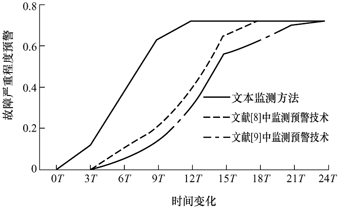
对比文献[8 ]中基于扩频编码的电磁探测技术和文献[9 ]中基于北斗卫星的在线监测方法,研究四种故障情况下的监测实时性和准确性。如图5 所示是发生故障情况1时,25 T 内监测实时性随时间变化的情况,T 表示单位时间长度,输电线从2 T 开始下垂,至10 T 下垂至l =8 m。
图5
由图5 可知,在2~10 T 发生传输线下垂的过程中,提出的监测方法相比文献[8 ,9 ]中方法具有更快的反应速度,在12 T 时间内准确计算输电杆塔的故障严重程度,相比另外两种方法,响应速度分别提高33.33%和42.86%。
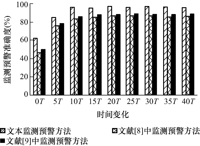
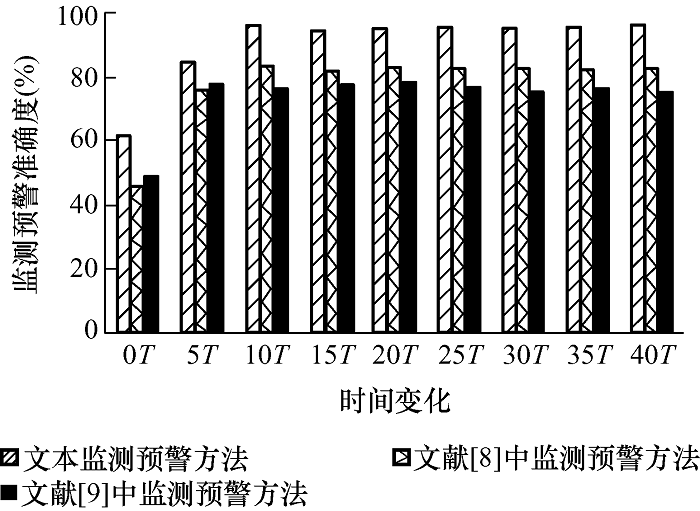
图6 、7分别为故障情况2、故障情况3发生时,所提方法与文献[8 ]、[9 ]中提出方法的准确性对比,令T =0时,发生故障。
图6
图7
由图6 、7 可知,本文提出的监测预警方法在发生中等及中等偏下程度的杆塔倾斜故障时,具有最快的反应速度,确认故障发生后的平均准确率分别为96.19%和96.17%。对比文献[8 ]、[9 ]中提出的方法,本文监测方法对于故障情况2中中等偏下程度的杆塔倾斜故障的平均监测预警准确率分别提高10.79%和8.66%,对于故障情况3中中等程度的杆塔倾斜故障的平均监测预警准确率分别提高13.21%和19.57%。对比现有方法,本文提出的监测预警方法显著提高了故障程度的监测准确度。
5 结论
针对已有输电杆塔倾斜监测方法判断标准单一、实时性差的问题,提出了一种基于磁场传感与北斗定位的采空区输电杆塔倾斜监测与预警方法。综合磁场传感器的磁通密度测量结果和北斗卫星定位技术,对磁通密度和输电杆塔倾斜程度进行双因素分级叠合,判断杆塔故障的严重程度等级,并进行预警,得出如下结论。
(1) 提出的采空区输电杆塔倾斜监测与预警方法,有效提高了故障监测响应速度和故障程度的监测准确度,在工程中对杆塔故障程度判定具有重要意义。
(2) 传感器的便携式平台便于工程人员快速简便地对已有杆塔升级改造,保证了在杆塔构件破坏、断裂、变形后的快速预警,有效预防故障跳闸、倒杆塔断线等严重事故的发生,减少经济损失。
参考文献
View Option
[1]
杨肖辉 , 张东 , 李晓光 , 等 . 750 kV输电线路风偏跳闸原因分析及改造措施研究
[J]. 电气工程学报 , 2017 ,12 (1 ):40 -46 .
[本文引用: 1]
YANG Xiaohui ZHANG Dong LI Xiaoguang , et al . Analysis and reform measures of 750 kV transmission line wind biased tripped
[J]. Journal of Electrical Engineering , 2017 ,12 (1 ):40 -46 .
[本文引用: 1]
[2]
XIANG Yukai CHEN Kunlong XU Qifeng , et al . A novel contactless current sensor for HVDC overhead transmission lines
[J]. IEEE Sensors Journal , 2018 ,18 (11 ):4725 -4732 .
DOI:10.1109/JSEN.2018.2828807
URL
[本文引用: 1]
[3]
王博闻 , 陆佳政 , 方针 , 等 . 一种10 kV配电线路防雷复合绝缘子的绝缘设计及防雷性能
[J]. 电网技术 , 2018 ,42 (6 ):2001 -2008 .
[本文引用: 1]
WANG Bowen LU Jiazheng FANG Zhen , et al . Study on insulation design and lightning protection performance of lightning protection composite insulators for 10 kV distribution line
[J]. Power System Technology , 2018 ,42 (6 ):2001 -2008 .
[本文引用: 1]
[4]
SHU Qianjin YUAN Guanglin JIA Leiliang , et al . A new simple design method for the plate foundation of a transmission tower in subsidence area
[J]. Open Civil Engineering Journal , 2016 ,10 (1 ):251 -265 .
DOI:10.2174/1874149501610010251
URL
[本文引用: 1]
[5]
王海涛 , 谷山强 , 吴大伟 , 等 . 基于数值天气预报的输电线路风偏闪络预警方法
[J]. 电力系统保护与控制 , 2017 ,45 (12 ):121 -127 .
[本文引用: 1]
WANG Haitao GU Shanqiang WU Dawei , et al . Method for windage yaw flashover warning of transmission lines based on numerical weather prediction
[J]. Power System Protection and Control , 2017 ,45 (12 ):121 -127 .
[本文引用: 1]
[6]
CHEN Daopin CHEN Zhucheng WANG Junbo , et al . Monitoring technology of scattered current in transmission line tower
[C]// 2017 2nd IEEE International Conference on Integrated Circuits and Microsystems (ICICM). IEEE, 2017 .
[本文引用: 1]
[7]
彭向阳 , 梁福逊 , 钱金菊 , 等 . 基于机载红外影像纹理特征的输电线路绝缘子自动定位
[J]. 高电压技术 , 2019 ,45 (3 ):922 -928 .
[本文引用: 1]
PENG Xiangyang LIANG Fuxun QIAN Jinju , et al . Automatic recognition of insulator from UAV infrared image based on periodic textural feature
[J]. High Voltage Engineering , 2019 ,45 (3 ):922 -928 .
[本文引用: 1]
[8]
楼文娟 , 吴登国 , 苏杰 , 等 . 超高压输电线路风偏闪络及导线风荷载取值讨论
[J]. 高电压技术 , 2019 ,45 (4 ):1249 -1255 .
[本文引用: 5]
LOU Wenjuan WU Dengguo SU Jie , et al . Discussion on wind-induced swing flashover and conductor wind load of EHV transmission lines
[J]. High Voltage Engineering , 2019 ,45 (4 ):1249 -1255 .
[本文引用: 5]
[9]
张来福 , 李士强 , 刘国强 , 等 . 基于扩频编码的电磁探测系统研究
[J]. 电工技术学报 , 2018 ,33 (S2 ):13 -19 .
[本文引用: 5]
ZHANG Laifu LI Shiqiang LIU Guoqiang , et al . Research on electromagnetic detection system for spread spectrum code
[J]. Transactions of China Electrotechnical Society , 2018 ,33 (S2 ):13 -19 .
[本文引用: 5]
[10]
邓召魁 , 吕玉祥 , 高存博 , 等 . 基于北斗卫星的输电杆塔在线监测系统
[J]. 现代电子技术 , 2016 ,39 (10 ):162 -166 .
[本文引用: 1]
DENG Zhaokui LÜ Yuxiang GAO Cunbo , et al . Beidou satellite based online monitoring system for power transmission tower
[J]. Modern Electronics Technique , 2016 ,39 (10 ):162 -166 .
[本文引用: 1]
[11]
杨风利 , 杨靖波 , 韩军科 , 等 . 煤矿采空区基础变形特高压输电塔的承载力计算
[J]. 中国电机工程学报 , 2009 ,29 (1 ):102 -108 .
[本文引用: 1]
YANG Fengli YANG Jingbo HAN Junke , et al . Beating capacity computation of UHV transmission tower with foundation deformation above coaf of goal mine
[J]. Proceedings of the CSEE , 2009 ,29 (1 ):102 -108 .
[本文引用: 1]
[12]
LIU H LIU C ZHAO Y , et al . Reverse catenary equation of the embedded installation line and application to the kinematic model for drag anchors
[J]. Applied Ocean Research , 2013 ,43 :80 -87 .
DOI:10.1016/j.apor.2013.08.002
URL
[本文引用: 1]
The penetration behavior and trajectory of the drag anchor in seabed soils are not only determined by properties of the anchor and soil, but also controlled by the installation line especially the segment embedded in the soil. Correctly understanding and describing reverse catenary properties of the embedded line are crucial for improving the drag embedment performance. precisely predicting the anchor trajectory. and solving the positioning problem in offshore applications. The investigation on reverse catenary problems demonstrates that, the reverse catenary shape of the embedded line has to be solved almost through numerical incremental methods. In the present study, based on the mechanical model for 1 he embedded line, the relationship between the tension and geometry of the embedded line, and the interactional equation between the anchor and embedded line are derived. By introducing the concept of the initial embedment depth of the installation line, the reverse catenary equation and the expression lot calculating the length of the embedded line are obtained for soils with a linear strength, and the position of the embedment point can be reasonably solved through the derived reverse catenary equation. The reverse catenary equation is then introduced into the kinematic model for drag anchors, which combines the drag anchor, the installation line and the movement of the anchor handling vessel being an interactional system. More information related to the drag embedment problem can be definitely gained through the present work, including not only the anchor behaviors such as the trajectory, penetration direction and ultimate embedment depth, but also the properties of the installation fine for both the embedded and horizontal segments. By comparing with drum centrifuge tests and model flume experiments. the efficiency of the theoretical method for predicting the anchor trajectory is well verified. (C) 2013 Elsevier Ltd.
[13]
LOPEZ-GARCIA O CARNICERO A TORRES V . Computation of the initial equilibrium of railway overheads based on the catenary equation
[J]. Engineering Structures , 2006 ,28 (10 ):1387 -1394 .
DOI:10.1016/j.engstruct.2006.01.007
URL
[本文引用: 1]
Abstract A formulation based on the analytical catenary equation has been implemented to obtain the initial equilibrium state of railway overheads. Due to the intrinsic nonlinear behavior of catenaries, the Newton–Raphson method has been chosen to find the solution. The herein presented method provides fast, accurate and robust initial equilibrium conditions which can be readily plugged into other numerical methods to simulate the catenary–pantograph interaction dynamics. Moreover, the size of the resulting problem is only dependent on the number of droppers and spans of the catenary, which leads to a minimum size problem when it is compared to other numerical methods. The validity and accuracy of the method have been proved by comparing computed results to published results. The results show excellent agreement with the comparison data.
[14]
戴聪 , 刘勇智 , 李杰 . 开关磁阻电机位置传感器机械偏移故障诊断和容错控制
[J]. 电子测量与仪器学报 , 2018 ,32 (9 ):12 -19 .
[本文引用: 1]
DAI Cong LIU Zhiyong LI Jie . Mechanical deviation fault diagnosis and tolerant control on position sensor in switched reluctance motor
[J]. Journal of Electronic Measurement and Instrumentation , 2018 ,32 (9 ):12 -19 .
[本文引用: 1]
[15]
王军庄 . 核电站对时系统设计优化
[J]. 电气工程学报 , 2018 ,13 (2 ):41 -44,50 .
[本文引用: 1]
WANG Junzhuang . Design and optimization of time synchronizing system in nuclear power station
[J]. Journal of Electrical Engineering , 2018 ,13 (2 ):41 -44,50 .
[本文引用: 1]
[16]
ZHU Gongsheng PEI Chunmei CAI Zhifang . Application of Beidou positioning and navigation technology in power transmission and transformation enterprises
[C]// IOP Conference Series:Materials Science and Engineering, 2019 ,490 (7 ):072040 .
[本文引用: 1]
750 kV输电线路风偏跳闸原因分析及改造措施研究
1
2017
... 随着电网向特高压大电网不断发展,输电线路的安全运行涉及多项经济、技术指标.其中,采空区因地质倾斜与沉降产生的非荷载应力将极有可能导致杆塔构件破坏、断裂、变形,造成电气安全距离不够、故障跳闸、倒杆塔断线等严重事故的发生[1 ,2 ] . ...
750 kV输电线路风偏跳闸原因分析及改造措施研究
1
2017
... 随着电网向特高压大电网不断发展,输电线路的安全运行涉及多项经济、技术指标.其中,采空区因地质倾斜与沉降产生的非荷载应力将极有可能导致杆塔构件破坏、断裂、变形,造成电气安全距离不够、故障跳闸、倒杆塔断线等严重事故的发生[1 ,2 ] . ...
A novel contactless current sensor for HVDC overhead transmission lines
1
2018
... 随着电网向特高压大电网不断发展,输电线路的安全运行涉及多项经济、技术指标.其中,采空区因地质倾斜与沉降产生的非荷载应力将极有可能导致杆塔构件破坏、断裂、变形,造成电气安全距离不够、故障跳闸、倒杆塔断线等严重事故的发生[1 ,2 ] . ...
一种10 kV配电线路防雷复合绝缘子的绝缘设计及防雷性能
1
2018
... 为了保证输电线路的安全稳定运行,已有研究提出多种针对防雷绝缘[3 ] 、形变倾斜[4 ] 、风偏闪络[5 ] 等的监测防治方案.如文献[6 ]研究了基于地面散射电流的分散式监测技术,但这一方案主要保障了在线监测的有效可靠,对离线监测没有突出的改进;文献[7 ]通过特征聚类实现了输电线路绝缘子的红外定位及自动辨识,但这一方案过度依赖先验参数的选取且不具有普遍适用性;文献[8 ]建立了四跨绝缘子串-导线耦合体系有限元模型以确定输电线路的风偏闪络,但拟合公式的方法计算结果较正常值小,而刚性直棒法没有考虑风速的脉动影响. ...
A new simple design method for the plate foundation of a transmission tower in subsidence area
1
2016
... 为了保证输电线路的安全稳定运行,已有研究提出多种针对防雷绝缘[3 ] 、形变倾斜[4 ] 、风偏闪络[5 ] 等的监测防治方案.如文献[6 ]研究了基于地面散射电流的分散式监测技术,但这一方案主要保障了在线监测的有效可靠,对离线监测没有突出的改进;文献[7 ]通过特征聚类实现了输电线路绝缘子的红外定位及自动辨识,但这一方案过度依赖先验参数的选取且不具有普遍适用性;文献[8 ]建立了四跨绝缘子串-导线耦合体系有限元模型以确定输电线路的风偏闪络,但拟合公式的方法计算结果较正常值小,而刚性直棒法没有考虑风速的脉动影响. ...
基于数值天气预报的输电线路风偏闪络预警方法
1
2017
... 为了保证输电线路的安全稳定运行,已有研究提出多种针对防雷绝缘[3 ] 、形变倾斜[4 ] 、风偏闪络[5 ] 等的监测防治方案.如文献[6 ]研究了基于地面散射电流的分散式监测技术,但这一方案主要保障了在线监测的有效可靠,对离线监测没有突出的改进;文献[7 ]通过特征聚类实现了输电线路绝缘子的红外定位及自动辨识,但这一方案过度依赖先验参数的选取且不具有普遍适用性;文献[8 ]建立了四跨绝缘子串-导线耦合体系有限元模型以确定输电线路的风偏闪络,但拟合公式的方法计算结果较正常值小,而刚性直棒法没有考虑风速的脉动影响. ...
基于数值天气预报的输电线路风偏闪络预警方法
1
2017
... 为了保证输电线路的安全稳定运行,已有研究提出多种针对防雷绝缘[3 ] 、形变倾斜[4 ] 、风偏闪络[5 ] 等的监测防治方案.如文献[6 ]研究了基于地面散射电流的分散式监测技术,但这一方案主要保障了在线监测的有效可靠,对离线监测没有突出的改进;文献[7 ]通过特征聚类实现了输电线路绝缘子的红外定位及自动辨识,但这一方案过度依赖先验参数的选取且不具有普遍适用性;文献[8 ]建立了四跨绝缘子串-导线耦合体系有限元模型以确定输电线路的风偏闪络,但拟合公式的方法计算结果较正常值小,而刚性直棒法没有考虑风速的脉动影响. ...
Monitoring technology of scattered current in transmission line tower
1
2017
... 为了保证输电线路的安全稳定运行,已有研究提出多种针对防雷绝缘[3 ] 、形变倾斜[4 ] 、风偏闪络[5 ] 等的监测防治方案.如文献[6 ]研究了基于地面散射电流的分散式监测技术,但这一方案主要保障了在线监测的有效可靠,对离线监测没有突出的改进;文献[7 ]通过特征聚类实现了输电线路绝缘子的红外定位及自动辨识,但这一方案过度依赖先验参数的选取且不具有普遍适用性;文献[8 ]建立了四跨绝缘子串-导线耦合体系有限元模型以确定输电线路的风偏闪络,但拟合公式的方法计算结果较正常值小,而刚性直棒法没有考虑风速的脉动影响. ...
基于机载红外影像纹理特征的输电线路绝缘子自动定位
1
2019
... 为了保证输电线路的安全稳定运行,已有研究提出多种针对防雷绝缘[3 ] 、形变倾斜[4 ] 、风偏闪络[5 ] 等的监测防治方案.如文献[6 ]研究了基于地面散射电流的分散式监测技术,但这一方案主要保障了在线监测的有效可靠,对离线监测没有突出的改进;文献[7 ]通过特征聚类实现了输电线路绝缘子的红外定位及自动辨识,但这一方案过度依赖先验参数的选取且不具有普遍适用性;文献[8 ]建立了四跨绝缘子串-导线耦合体系有限元模型以确定输电线路的风偏闪络,但拟合公式的方法计算结果较正常值小,而刚性直棒法没有考虑风速的脉动影响. ...
基于机载红外影像纹理特征的输电线路绝缘子自动定位
1
2019
... 为了保证输电线路的安全稳定运行,已有研究提出多种针对防雷绝缘[3 ] 、形变倾斜[4 ] 、风偏闪络[5 ] 等的监测防治方案.如文献[6 ]研究了基于地面散射电流的分散式监测技术,但这一方案主要保障了在线监测的有效可靠,对离线监测没有突出的改进;文献[7 ]通过特征聚类实现了输电线路绝缘子的红外定位及自动辨识,但这一方案过度依赖先验参数的选取且不具有普遍适用性;文献[8 ]建立了四跨绝缘子串-导线耦合体系有限元模型以确定输电线路的风偏闪络,但拟合公式的方法计算结果较正常值小,而刚性直棒法没有考虑风速的脉动影响. ...
超高压输电线路风偏闪络及导线风荷载取值讨论
5
2019
... 为了保证输电线路的安全稳定运行,已有研究提出多种针对防雷绝缘[3 ] 、形变倾斜[4 ] 、风偏闪络[5 ] 等的监测防治方案.如文献[6 ]研究了基于地面散射电流的分散式监测技术,但这一方案主要保障了在线监测的有效可靠,对离线监测没有突出的改进;文献[7 ]通过特征聚类实现了输电线路绝缘子的红外定位及自动辨识,但这一方案过度依赖先验参数的选取且不具有普遍适用性;文献[8 ]建立了四跨绝缘子串-导线耦合体系有限元模型以确定输电线路的风偏闪络,但拟合公式的方法计算结果较正常值小,而刚性直棒法没有考虑风速的脉动影响. ...
... 对比文献[8 ]中基于扩频编码的电磁探测技术和文献[9 ]中基于北斗卫星的在线监测方法,研究四种故障情况下的监测实时性和准确性.如图5 所示是发生故障情况1时,25 T 内监测实时性随时间变化的情况,T 表示单位时间长度,输电线从2 T 开始下垂,至10 T 下垂至l =8 m. ...
... 由图5 可知,在2~10 T 发生传输线下垂的过程中,提出的监测方法相比文献[8 ,9 ]中方法具有更快的反应速度,在12 T 时间内准确计算输电杆塔的故障严重程度,相比另外两种方法,响应速度分别提高33.33%和42.86%. ...
... 图6 、7分别为故障情况2、故障情况3发生时,所提方法与文献[8 ]、[9 ]中提出方法的准确性对比,令T =0时,发生故障. ...
... 由图6 、7 可知,本文提出的监测预警方法在发生中等及中等偏下程度的杆塔倾斜故障时,具有最快的反应速度,确认故障发生后的平均准确率分别为96.19%和96.17%.对比文献[8 ]、[9 ]中提出的方法,本文监测方法对于故障情况2中中等偏下程度的杆塔倾斜故障的平均监测预警准确率分别提高10.79%和8.66%,对于故障情况3中中等程度的杆塔倾斜故障的平均监测预警准确率分别提高13.21%和19.57%.对比现有方法,本文提出的监测预警方法显著提高了故障程度的监测准确度. ...
基于扩频编码的电磁探测系统研究
5
2018
... 采空区的地表会发生塌陷或水平移动的地质形态改变,这一地质变化更易造成输电杆塔的倾斜与基础不均匀沉降,导致输电杆塔发生严重的电气事故.针对这一区域的输电杆塔监测,文献[9 ]提出基于扩频编码的电磁探测系统,实现采空区的有效勘探,虽然提高了探测效率,但电磁探测系统准确度的提高以强发射功率为代价,经济性差;文献[10 ]基于北斗卫星实现输电杆塔的在线监测,但这一方案不能满足离线状态下的数据分析要求;文献[11 ]通过采空区输电杆塔的承载力计算,判断倾斜位移的安全范围,这一方案虽然为安全运行提供参考依据,但不能对杆塔状态进行在线监测. ...
... 对比文献[8 ]中基于扩频编码的电磁探测技术和文献[9 ]中基于北斗卫星的在线监测方法,研究四种故障情况下的监测实时性和准确性.如图5 所示是发生故障情况1时,25 T 内监测实时性随时间变化的情况,T 表示单位时间长度,输电线从2 T 开始下垂,至10 T 下垂至l =8 m. ...
... 由图5 可知,在2~10 T 发生传输线下垂的过程中,提出的监测方法相比文献[8 ,9 ]中方法具有更快的反应速度,在12 T 时间内准确计算输电杆塔的故障严重程度,相比另外两种方法,响应速度分别提高33.33%和42.86%. ...
... 图6 、7分别为故障情况2、故障情况3发生时,所提方法与文献[8 ]、[9 ]中提出方法的准确性对比,令T =0时,发生故障. ...
... 由图6 、7 可知,本文提出的监测预警方法在发生中等及中等偏下程度的杆塔倾斜故障时,具有最快的反应速度,确认故障发生后的平均准确率分别为96.19%和96.17%.对比文献[8 ]、[9 ]中提出的方法,本文监测方法对于故障情况2中中等偏下程度的杆塔倾斜故障的平均监测预警准确率分别提高10.79%和8.66%,对于故障情况3中中等程度的杆塔倾斜故障的平均监测预警准确率分别提高13.21%和19.57%.对比现有方法,本文提出的监测预警方法显著提高了故障程度的监测准确度. ...
基于北斗卫星的输电杆塔在线监测系统
1
2016
... 采空区的地表会发生塌陷或水平移动的地质形态改变,这一地质变化更易造成输电杆塔的倾斜与基础不均匀沉降,导致输电杆塔发生严重的电气事故.针对这一区域的输电杆塔监测,文献[9 ]提出基于扩频编码的电磁探测系统,实现采空区的有效勘探,虽然提高了探测效率,但电磁探测系统准确度的提高以强发射功率为代价,经济性差;文献[10 ]基于北斗卫星实现输电杆塔的在线监测,但这一方案不能满足离线状态下的数据分析要求;文献[11 ]通过采空区输电杆塔的承载力计算,判断倾斜位移的安全范围,这一方案虽然为安全运行提供参考依据,但不能对杆塔状态进行在线监测. ...
基于北斗卫星的输电杆塔在线监测系统
1
2016
... 采空区的地表会发生塌陷或水平移动的地质形态改变,这一地质变化更易造成输电杆塔的倾斜与基础不均匀沉降,导致输电杆塔发生严重的电气事故.针对这一区域的输电杆塔监测,文献[9 ]提出基于扩频编码的电磁探测系统,实现采空区的有效勘探,虽然提高了探测效率,但电磁探测系统准确度的提高以强发射功率为代价,经济性差;文献[10 ]基于北斗卫星实现输电杆塔的在线监测,但这一方案不能满足离线状态下的数据分析要求;文献[11 ]通过采空区输电杆塔的承载力计算,判断倾斜位移的安全范围,这一方案虽然为安全运行提供参考依据,但不能对杆塔状态进行在线监测. ...
煤矿采空区基础变形特高压输电塔的承载力计算
1
2009
... 采空区的地表会发生塌陷或水平移动的地质形态改变,这一地质变化更易造成输电杆塔的倾斜与基础不均匀沉降,导致输电杆塔发生严重的电气事故.针对这一区域的输电杆塔监测,文献[9 ]提出基于扩频编码的电磁探测系统,实现采空区的有效勘探,虽然提高了探测效率,但电磁探测系统准确度的提高以强发射功率为代价,经济性差;文献[10 ]基于北斗卫星实现输电杆塔的在线监测,但这一方案不能满足离线状态下的数据分析要求;文献[11 ]通过采空区输电杆塔的承载力计算,判断倾斜位移的安全范围,这一方案虽然为安全运行提供参考依据,但不能对杆塔状态进行在线监测. ...
Reverse catenary equation of the embedded installation line and application to the kinematic model for drag anchors
1
2013
... 使用抛物线近似来描述传输线曲线,悬链线方程的近似值如文献[12 ,13 ]所述,传输线B在x -y 平面中,并且相对于y 轴对称分布 ...
Computation of the initial equilibrium of railway overheads based on the catenary equation
1
2006
... 使用抛物线近似来描述传输线曲线,悬链线方程的近似值如文献[12 ,13 ]所述,传输线B在x -y 平面中,并且相对于y 轴对称分布 ...
开关磁阻电机位置传感器机械偏移故障诊断和容错控制
1
2018
... 磁阻传感器可以测量地面传输线下的磁通密度,进而得到磁场分布,这里使用具有低成本、低功耗和高检测精度的隧道磁阻(Tunneling magnetoresistive,TMR)[14 ] ,测得的磁场通过人工免疫系统算法的优化方法迭代更新,即可得到υ 、γ 和传输线垂度.首先根据υ 、γ 和传输线垂度求出预存储位置系数矩阵A ,然后通过最小二乘估计法计算三相电流,推导出磁通密度,最后将计算出的和测得的磁场数据之间的绝对误差与精度阈值相比较,通过AIS算法更新预存储位置系数矩阵A ,直到计算数据的和测得的磁场数据之间的绝对误差小于精度阈值,即得到准确的监测磁通值,监测磁通值的波动情况和其对应杆塔倾斜监测预警的影响因子GI 如表1 所示. ...
核电站对时系统设计优化
1
2018
... 输电杆塔的北斗定位监测点如图4 所示,选取杆塔附近30 km范围的稳定基岩,作为毫米级监测要求的基准站[15 ,16 ] ,并埋设相对塔基位置固定且稳定的观测墩,以确保基准点的坐标固定不变. ...
核电站对时系统设计优化
1
2018
... 输电杆塔的北斗定位监测点如图4 所示,选取杆塔附近30 km范围的稳定基岩,作为毫米级监测要求的基准站[15 ,16 ] ,并埋设相对塔基位置固定且稳定的观测墩,以确保基准点的坐标固定不变. ...
Application of Beidou positioning and navigation technology in power transmission and transformation enterprises
1
2019
... 输电杆塔的北斗定位监测点如图4 所示,选取杆塔附近30 km范围的稳定基岩,作为毫米级监测要求的基准站[15 ,16 ] ,并埋设相对塔基位置固定且稳定的观测墩,以确保基准点的坐标固定不变. ...


