1 引言
很多国家或地区将化石燃料作为生产电能的主要来源,导致环境污染和能源短缺问题日益严峻[1 ] 。传统大电网对于偏远地区输电的局限性日益凸显,由于传输距离较远,线路阻抗造成的电力损耗十分巨大[2 ] 。太阳能、风能等可再生资源的开发利用与由其组成的微电网在改善大电网系统供能方面潜力巨大,得到广泛重视[3 ] 。逆变器作为直流母线到交流负载的功率变换和能量控制的接口单元,为分布式可再生能源的利用提供了途径。由于诸多因素的限制,单台逆变器已不能满足系统容量的需求。多台逆变器并联可以提高系统容量、增加系统冗余、提高供电可靠性、增强系统灵活性[4 ] 。但多逆变器并联运行要求各逆变器的输出电压无压差,并且频率和相位一致。实际应用中,由于系统设备存在差异、硬件参数不同、开关动作不一致等因素,为逆变器并联带来一些困难,导致并联逆变器系统内部形成环流,使得功率分配不均,影响系统稳定可靠运行,因此对系统内部环流进行抑制就显得十分必要[5 ,6 ] 。
下垂控制由于不需要逆变器之间进行通信线连接,各逆变器既可以独立运行也可以并联运行,并且单台出现故障也不会影响系统内其他逆变器正常运行,其“即插即用”或“热插拔”的优势得到了广泛认可[7 ,8 ] 。在对下垂控制进行分析的时候,一般假定系统线路阻抗为纯阻性或纯感性,但在低压微电网当中线路阻抗往往呈阻感特征,这使系统输出有功功率和无功功率出现耦合。为实现功率解耦控制,文献[9 ]通过比例谐振闭环控制器调节逆变器输出阻抗为零,避免了功率耦合对输出电流的影响,但仿真与试验均未考虑线路阻抗不匹配的情形;文献[10 ]提出等效参考电流控制法,通过对电流参考值与实际值的偏差进行控制,实现了并离网间的平滑切换;文献[11 ]在传统控制中分别引入功率、下垂系数一次函数项和微分项,实现了下垂系数随功率变化的动态调整,同时提高了系统稳定性与动态响应;文献[12 ,13 ,14 ,15 ,16 ,17 ]通过在控制系统中引入虚拟阻抗环,调节等效输出阻抗呈所需特性实现功率解耦;文献[18 ,19 ]对其虚拟阻抗导致的压降进行补偿,提升了输出电压质量;文献[20 ]针对虚拟阻抗造成逆变器出口电压下降的问题,将等效输出阻抗视为虚拟同步发电机电抗,删除无功功率-电压控制环,简化了控制结构;文献[21 ]通过引入虚拟功率得出线路阻感比与下垂控制的耦合关系,增加虚拟阻抗控制环进行功率解耦,实现功率均分;文献[22 ]提出了一种基于虚拟阻抗的并联逆变器主从控制方法对环流进行抑制。
本文在分析了逆变器输出功率传输特性以及环流的产生与影响因素基础上,采用虚拟复阻抗方法,对微网系统环流进行抑制。考虑到输出电压与等效输出阻抗的关系,进一步提出动态虚拟复阻抗方法来抑制环流,并通过仿真验证了所提方法的可行性。
2 功率传输特性分析
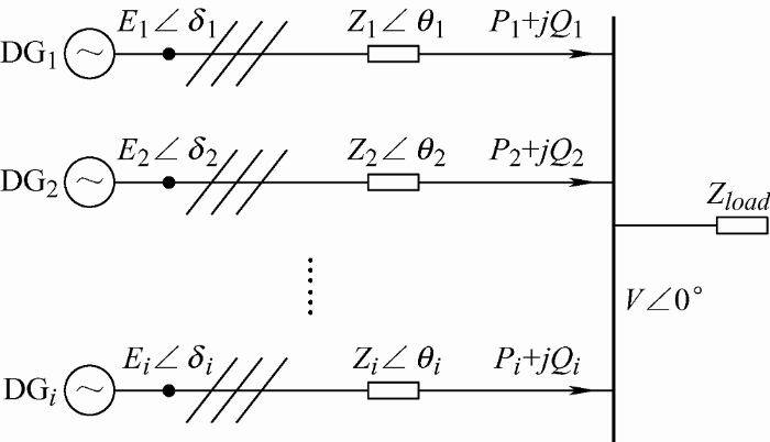
下垂控制方式中,并联系统各逆变器通过采集自身信号调节输出特性,逆变器之间无需通信线连接。图1 为连接到公共母线的多逆变器简化电路示意图。
图1
从图1 可得逆变器输出相电流、有功功率、无功功率分别如式(1)、(2)所示
(1) $\begin{align} & {{{\dot{I}}}_{i}}=\frac{{{E}_{i}}\angle {{\delta }_{i}}-V\angle 0{}^\circ }{{{Z}_{i}}\angle {{\theta }_{i}}}=\frac{{{E}_{i}}\angle ({{\delta }_{i}}-{{\theta }_{i}})}{\left| {{Z}_{i}} \right|}-\frac{V\angle (-{{\theta }_{i}})}{\left| {{Z}_{i}} \right|}= \\ & \ \ \frac{{{E}_{i}}\cos ({{\delta }_{i}}-{{\theta }_{i}})-V\cos ({{\theta }_{i}})}{\left| {{Z}_{i}} \right|}+ \\ & \ \ j\frac{{{E}_{i}}\sin ({{\delta }_{i}}-{{\theta }_{i}})+V\sin ({{\theta }_{i}})}{\left| {{Z}_{i}} \right|} \end{align}$
式中,V ∠0°为交流母线端压(以交流母线电压相位为参考相位);Ei ∠δi 为逆变器端的输出电压;δi 为逆变器端输出电压与交流母线电压相角差;第i 台逆变器等效输出阻抗为Zi ∠θi =Ri +jωLi ,其中包括逆变器输出阻抗和线路阻抗,θi 为等效输出阻抗角;Zload 为并联逆变器公共负载;Si =Pi +jQi 为第i 台逆变器输出复功率,其中Pi ,Qi 分别为对应的有功功率和无功功率。
(2) $\left\{ \begin{matrix} {{P}_{i}}=\frac{3V}{\left| {{Z}_{i}} \right|}[{{E}_{i}}\cos {{\delta }_{i}}-{{\theta }_{i}})-V\cos {{\theta }_{i}}] \\ {{Q}_{i}}=-\frac{3V}{\left| {{Z}_{i}} \right|}[{{E}_{i}}\sin ({{\delta }_{i}}-{{\theta }_{i}})+V\sin {{\theta }_{i}}] \\ \end{matrix} \right.$
由式(2)可以看到,Pi ,Qi 同时受到Ei ,δi 的影响,造成控制系统耦合。下垂控制的主要目的是使并联逆变器所承担的功率实现合理分配,并期望以Pi ,Qi 作为被控制对象,以Ei ,δi 作为控制对象的单输入单输出系统,因此需要对控制系统进行解耦。
由于连线阻抗远小于负载阻抗,通常情况下相角差δi 很小,因此sinδi ≈δi ,cosδi ≈1。低压线路阻抗以阻性成分为主,假设系统输出阻抗为纯阻性,则可认为θi =arctan(ωLi /Ri )。
对Pi ,Qi 分别求Ei ,δi 的偏导数并简化得式(3),在输出阻抗为纯阻性的低压系统中,逆变器电压相位变化和输出无功功率相关,电压幅值变化和输出有功功率相关。由于ωi =dδi /dt ,因此可以通过改变逆变器电压幅值控制有功功率输出,改变电压角频率间接改变相位控制无功功率输出。
(3) $\left\{ \begin{align} & \frac{\partial {{P}_{i}}}{\partial {{\delta }_{i}}}=\frac{3V{{E}_{i}}}{\left| {{Z}_{i}} \right|}\sin ({{\theta }_{i}}-{{\delta }_{i}})\approx 0 \\ & \frac{\partial {{P}_{i}}}{\partial {{E}_{i}}}=\frac{3V}{\left| {{Z}_{i}} \right|}\cos ({{\theta }_{i}}-{{\delta }_{i}})\approx \frac{3V}{\left| {{Z}_{i}} \right|} \\ & \frac{\partial {{Q}_{i}}}{\partial {{\delta }_{i}}}=-\frac{3V{{E}_{i}}}{\left| {{Z}_{i}} \right|}\cos ({{\theta }_{i}}-{{\delta }_{i}})\approx -\frac{3V{{E}_{i}}}{\left| {{Z}_{i}} \right|} \\ & \frac{\partial {{Q}_{i}}}{\partial {{E}_{i}}}=\frac{3V}{\left| {{Z}_{i}} \right|}\sin ({{\theta }_{i}}-{{\delta }_{i}})\approx 0 \\ \end{align} \right.$
由于∂Qi / ∂δi 为负值,因此可认为Qi 与-δi 相关,为了使QF 环形成负反馈,kQi Qi 之前的符号须为“+”,从而使该项成为增加项。传统的PV-QF 下垂控制方式如式(4)所示
(4) $\left\{ \begin{matrix} {{E}_{i}}={{V}_{i}}^{*}-{{k}_{P}}_{i}{{P}_{i}} \\ {{\omega }_{i}}={{\omega }_{i}}^{*}+{{k}_{Q}}_{i}{{Q}_{i}} \\ \end{matrix} \right.$
式中,Ei ,ωi 分别为逆变器实际输出电压幅值和角频率;Vi * ,ωi * 分别为逆变器输出电压幅值和角频率的参考值;Pi ,Qi 分别为逆变器实际输出有功功率和无功功率;Pi * ,Qi * 分别为逆变器输出有功功率和无功功率的参考值;kPi ,kQi 分别为对应的有功功率和无功功率下垂系数。
3 控制回路设计及输出阻抗分析
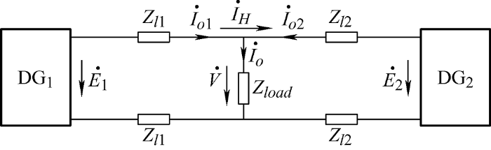
为简化分析,设系统由两台逆变器并联组成,其简化电路如图2 所示。
图2
图2 中${{\dot{E}}_{i}}$,${{\dot{I}}_{oi}}$,${{\dot{I}}_{H}}$,${{Z}_{li}}$(i =1, 2)分别表示两台逆变器输出电压、输出电流、环流、线路阻抗;$\dot{V}$,${{\dot{I}}_{o}}$分别表示公共负载两端电压与流过负载的总电流。
(5) $\left\{ \begin{align} & {{{\dot{E}}}_{1}}-\dot{V}=2{{Z}_{l1}}{{{\dot{I}}}_{o1}} \\ & {{{\dot{E}}}_{2}}-\dot{V}=2{{Z}_{l2}}{{{\dot{I}}}_{o2}} \\ & {{{\dot{I}}}_{o1}}+{{{\dot{I}}}_{o2}}=\frac{{\dot{V}}}{{{Z}_{load}}} \\ \end{align} \right.$
(6) $\begin{align} & \dot{V}=\frac{2{{Z}_{l2}}{{Z}_{load}}}{2{{Z}_{l1}}{{Z}_{load}}+2{{Z}_{l2}}{{Z}_{load}}+4{{Z}_{l1}}{{Z}_{l2}}}{{{\dot{E}}}_{1}}+ \\ & \ \ \frac{2{{Z}_{l1}}{{Z}_{load}}}{2{{Z}_{l1}}{{Z}_{load}}+2{{Z}_{l2}}{{Z}_{load}}+4{{Z}_{l1}}{{Z}_{l2}}}{{{\dot{E}}}_{2}} \end{align}$
(7) $\begin{align} & {{{\dot{I}}}_{o1}}=\frac{({{{\dot{E}}}_{1}}-\dot{V})}{2{{Z}_{l1}}}=\frac{2{{Z}_{l2}}+{{Z}_{load}}}{2{{Z}_{l1}}{{Z}_{load}}+2{{Z}_{l2}}{{Z}_{load}}+4{{Z}_{l1}}{{Z}_{l2}}}{{{\dot{E}}}_{1}}- \\ & \ \ \frac{{{Z}_{load}}}{2{{Z}_{l1}}{{Z}_{load}}+2{{Z}_{l2}}{{Z}_{load}}+4{{Z}_{l1}}{{Z}_{l2}}}{{{\dot{E}}}_{2}} \end{align}$
${{\dot{I}}_{o2}}$同理可得。假设线路阻抗为纯阻性且Zl 1 =Zl 2 =R 远小于Zload ,则交流母线电压与系统环流分别简化为式(8)和(9)
(8) $\dot{V}=\frac{2R{{Z}_{load}}}{4R{{Z}_{load}}+4{{R}^{2}}}({{\dot{E}}_{1}}+{{\dot{E}}_{2}}\approx \frac{({{{\dot{E}}}_{1}}+{{{\dot{E}}}_{2}}}{2}$
(9) $\begin{matrix} {{{\dot{I}}}_{H}}=\frac{({{{\dot{I}}}_{o1}}-{{{\dot{I}}}_{o2}})}{2}=\frac{R+{{Z}_{load}}}{4R{{Z}_{load}}+4{{R}^{2}}}({{{\dot{E}}}_{o1}}-{{{\dot{E}}}_{o2}})= \\ \frac{({{{\dot{E}}}_{o1}}-{{{\dot{E}}}_{o2}})}{4R}=\frac{\Delta {{{\dot{V}}}_{o}}}{4R} \\ \end{matrix}$
由式(9)可知,假设条件下系统环流只与电压偏差有关,若线路阻抗不相等,则阻抗偏差造成的电压幅值偏差将会引起较大的环流,这将对系统可靠稳定运行造成极大隐患,因此应减小阻抗偏差以抑制环流的产生。
逆变器通常采用电压电流双闭环控制方式,本文中电流内环以电容电流为控制对象,选用比例控制器(Gi (s )=kip ),以获得更快的动态响应;电压外环以电容电压为控制对象,选用比例积分控制器(Gv (s )= kvp+ kvi /s ),以提高系统的抗扰性。其中kip ,kvp 分别为比例控制器与积分控制器的比例系数,kvi 为积分控制器的积分系数。
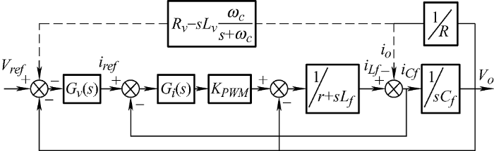
闭环控制的目的是实现系统输出电压对参考电压的动态跟踪,因此可将逆变器等效成一个含有内阻的受控电压源,引入虚拟复阻抗乘以逆变器输出电流反馈对参考电压进行修正,相当于将虚拟复阻抗与逆变器等效输出阻抗串联[5 ,6 ,7 ] ,因此在传统控制方式下引入适当的虚拟复阻抗Zv =Rv -jωLv (其中,Rv 为虚拟电阻,Lv 为虚拟电感且Lv =Li ),则引入虚拟复阻抗后的等效输出阻抗为Zv * =Rv +Ri ,在实现输出阻抗为纯阻性的同时,构造Zl 1 =Zl 2 =Rv 以改善各逆变器输出阻抗不一致问题。图3 为引入虚拟复阻抗的电压电流闭环控制框图,虚线为虚拟复阻抗环。
图3
由图3 可知,系统输出电压Vo (s )的传递函数如式(10)所示
(10) ${{V}_{o}}(s)=\frac{{{G}_{v}}(s){{G}_{i}}(s){{K}_{PWM}}{{V}_{ref}}(s)}{{{L}_{f}}{{C}_{f}}{{s}^{2}}+(r+{{G}_{i}}(s){{K}_{PWM}}){{C}_{f}}s+1+{{G}_{v}}(s){{G}_{i}}(s){{K}_{PWM}}}-\frac{({{L}_{f}}s+r+{{G}_{v}}(s){{G}_{i}}(s){{K}_{PWM}}{{Z}_{v}}){{i}_{o}}(s)}{{{L}_{f}}{{C}_{f}}{{s}^{2}}+(r+{{G}_{i}}(s){{K}_{PWM}}){{C}_{f}}s+1+{{G}_{v}}(s){{G}_{i}}(s){{K}_{PWM}}}$
式中,Lf 和r 分别为逆变器滤波电感及其寄生电阻;Cf 为滤波电容;Zv =Rv -sLv ωc /(s +ωc ),ωc 为一阶低通滤波器截止频率,加入滤波器的目的是滤除对电流微分引入的高频噪声[8 ] ;KPWM 为逆变器电流增益。对式(10)进行改写得式(11)
(11) Vo (s )=G (s )Vref (s )-(Zo (s)+G (s )Zv )io (s )
式中,G (s )为电压传递函数;Zo (s )为传统控制式下系统等效输出阻抗,引入虚拟复阻抗后的等效输出阻抗为Zo * (s )=Zo (s )+G (s )Zv 。
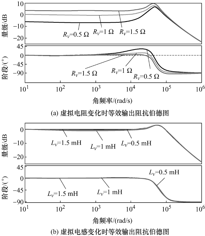
由表1 的下垂控制参数得到引入虚拟复阻抗的逆变器等效输出阻抗伯德图如图4 所示。
图4
从图4 a可知,引入虚拟复阻抗后,系统等效输出阻抗随着虚拟电阻的增大而增大,当取Rv =1时,等效输出阻抗几乎呈纯阻性;从图4 b可以看出,由于所加虚拟电感值(分别为0.5 mH、1.0 mH、1.5 mH)对系统输出阻抗影响不大,因此取Lv =1.0,使系统等效输出阻抗呈弱容性。
4 动态虚拟复阻抗方法
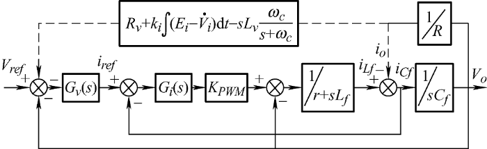
实际上,根据式(9)可知,加入虚拟复阻抗并不能完全抑制环流,因为稳态时逆变器输出电压幅值Ei 并不一致,考虑到电压与阻抗的反比例关系,本文将虚拟复阻抗中的虚拟电阻改为与输出电压关联的动态虚拟电阻(ki 为电压幅值差积分系数) ${{R}_{v}}^{*}={{R}_{v}}+{{k}_{i}}\int{({{E}_{i}}-{{V}_{i}}^{*})\text{d}t}$对输出电压幅值进行动态反向调整,以抑制电压幅值差带来的环流。根据电压质量要求,输出电压幅值${{E}_{i}}$不应超过额定电压的±5%,同时设定Rv * 的变化不超过额定值的±10%,取ki =0.3。图5 为引入动态虚拟复阻抗的电压电流闭环控制框图,虚线为动态虚拟复阻抗环。
图5
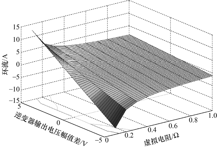
Rv * 的变化与逆变器输出电压幅值差对系统环流的影响如图6 所示,当随着逆变器输出电压幅值差的减小,系统环流随之减小; 随着Rv * 增大, 系统环流也随之减小。
图6
图6
Rv * 变化与逆变器输出电压幅值差对环流的影响
5 系统仿真与分析
为了验证所提的基于虚拟复阻抗的改进下垂控制方法在实现功率均分与环流抑制方面的正确性与有效性,在PSIM中搭建了仿真模型,该仿真模型在以两台电压源型三相逆变器并联系统离网模式下进行。仿真中设定两台相同容量逆变器并联到公共交流母线的传输阻抗不相等,逆变器输出电压为频率50 Hz峰值310 V的正弦波;滤波器电感电容取值见表1 。
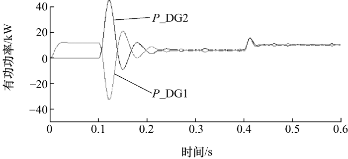
仿真过程:首先让DG1独立运行,负载大小为R 1 =10 Ω、L 1 =10 mH;t =0.1 s时直接并入DG2进行功率均分;t =0.4 s 时投入负载R 2 =1 Ω、L 2 = 10 mH,由两台逆变器共同承担负载。
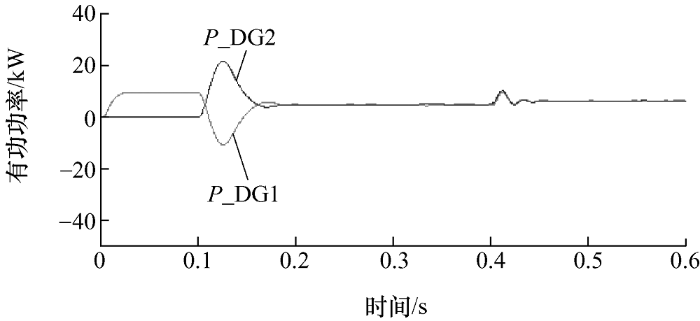
图7 、8分别为改进前后两台逆变器直接并联的有功功率分配情况。从图中可以看出在DG2直接并入时,传统控制方式下产生较大的功率振荡,稳态时功率表现出较强耦合性;改进后的控制方式下,在DG2直接并入时,功率振荡明显减小,响应速度提高,并且稳态时功率实现解耦,均分效果明显。
图7
图8
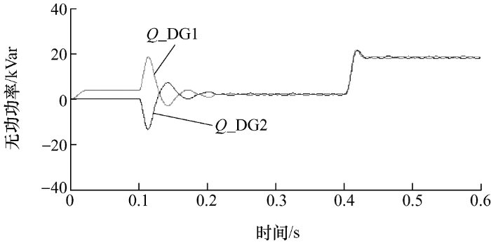
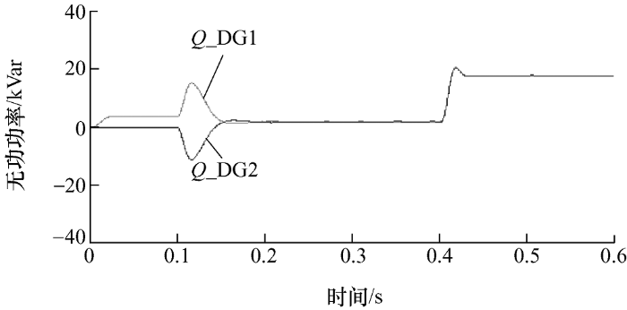
类似地,图9 、10 分别为改进前后两台逆变器直接并联的无功功率分配情况。
图9
图10
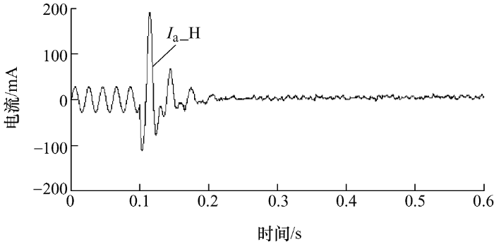
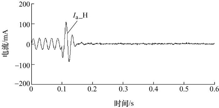
图11 、12 分别为改进前后两台逆变器直接并联的a相环流(0.1 s前环流无参考意义)。改进后的控制方式下并联冲击电流显著减小,响应速度加快,稳态时环流幅值进一步降低。
图11
图12
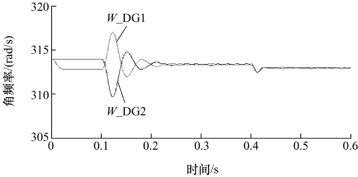
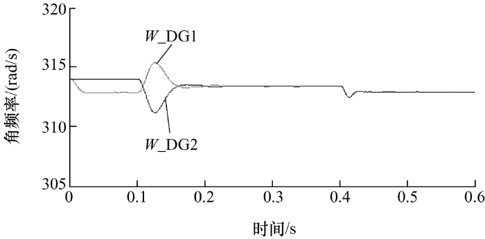
图13 、14分别为改进前后两台逆变器输出角频率。在改进后的控制方式下输出角频率波动减小,保证了无功功率的有效均分。
图13
图14
6 结论
本文提出了一种动态虚拟复阻抗方法,使逆变器输出电压幅值差动态调整虚拟复阻抗阻性部分。仿真验证了该方法能够在两台相同容量并联系统中有效减小环流,改善功率均分效果,提高系统的动态响应速度。在两台逆变器直接并联过程中明显抑制并联冲击。后续将搭建实物平台对所提方法进行试验验证。
参考文献
View Option
[1]
Van der Meer D Mouli G R C Morales-Espana G , et al . Energy management system with PV power forecast to optimally charge EVs at the workplace
[J]. IEEE Transactions on Industrial Informatics , 2016 ,14 (1 ):311 -320 .
DOI:10.1109/TII.2016.2634624
URL
[本文引用: 1]
[2]
Eid B M Rahim N A Selvaraj J , et al . Control methods and objectives for electronically coupled distributed energy resources in microgrids:A review
[J]. IEEE System Journal , 2016 ,10 (2 ):446 -458 .
DOI:10.1109/JSYST.2013.2296075
URL
[本文引用: 1]
[3]
Guo Li Zhang Shaohui Li Xialin , et al . Stability analysis and damping enhancement based on frequency-dependent virtual impedance for DC microgrids
[J]. IEEE Journal of Emerging & Selected Topics in Power Electronics , 2017 ,5 (1 ):338 -350 .
[本文引用: 1]
[4]
Yang Jie Jin Xinmin Wu Xuezhi , et al . Decentralized control method for DC microgrids with improved current sharing accuracy
[J]. IET Generation Transmission & Distribution , 2017 ,11 (3 ):696 -706 .
[本文引用: 1]
[5]
陈燕东 , 罗安 , 龙际根 , 等 . 阻性逆变器并联环流分析及鲁棒下垂多环控制
[J]. 中国电机工程学报 , 2013 ,33 (18 ):18 -29 .
URL
[本文引用: 2]
对于独立微电网中的并联逆变器,其等效输出阻抗和线路阻抗差异对功率分配和环流抑制存在较大影响。从逆变器并联的功率传输特性出发,分析现有下垂控制对阻性逆变器并联功率分配的影响,并在分析阻性逆变器环流特性的基础上,提出一种鲁棒下垂多环控制方法,其由功率外环和电压电流内环构成。功率外环采用鲁棒下垂控制器,减小阻抗差异对功率精确分配的影响;通过引入含阻性分量和感性分量的虚拟复阻抗,将逆变器的等效输出阻抗设计呈阻性;采用准谐振PR控制实现在较宽频带内逆变器输出电压的零稳态误差控制,进而减少逆变器间输出电压偏差并抑制环流。采用输出电压前馈和电容电流比例控制提高系统暂态响应和电流抗扰动能力。深入对比分析控制方式和控制参数对等效输出阻抗的影响,并择优选取控制参数。仿真和实验结果验证了所提提方法的正确性和有效性。
Chen Yandong Luo An Long Jigen , et al . Circulating current analysis and robust droop multiple loop control method for parallel inverters using resistive output impedance
[J]. Proceedings of the CSEE , 2013 ,33 (18 ):18 -29 .
URL
[本文引用: 2]
对于独立微电网中的并联逆变器,其等效输出阻抗和线路阻抗差异对功率分配和环流抑制存在较大影响。从逆变器并联的功率传输特性出发,分析现有下垂控制对阻性逆变器并联功率分配的影响,并在分析阻性逆变器环流特性的基础上,提出一种鲁棒下垂多环控制方法,其由功率外环和电压电流内环构成。功率外环采用鲁棒下垂控制器,减小阻抗差异对功率精确分配的影响;通过引入含阻性分量和感性分量的虚拟复阻抗,将逆变器的等效输出阻抗设计呈阻性;采用准谐振PR控制实现在较宽频带内逆变器输出电压的零稳态误差控制,进而减少逆变器间输出电压偏差并抑制环流。采用输出电压前馈和电容电流比例控制提高系统暂态响应和电流抗扰动能力。深入对比分析控制方式和控制参数对等效输出阻抗的影响,并择优选取控制参数。仿真和实验结果验证了所提提方法的正确性和有效性。
[6]
Xiao Huagen Luo A Shuai Zhikang , et al . An improved control method for multiple bidirectional power converters in hybrid AC/DC microgrid
[J]. IEEE Transactions on Smart Grid , 2016 ,7 (1 ):340 -347 .
DOI:10.1109/TSG.2015.2469758
URL
[本文引用: 2]
[7]
张庆海 , 彭楚武 , 陈燕东 , 等 . 一种微电网多逆变器并联运行控制策略
[J]. 中国电机工程学报 , 2012 ,32 (25 ):126 -132 .
URL
[本文引用: 2]
在微电网多逆变器并联系统中,由于逆变器的输出阻抗以及与公共连接点的线路阻抗存在差异,应用传统下垂控制法会导致逆变器间的环流较大及功率均分精度较低。在分析多逆变器并联系统中传统下垂控制法及逆变器输出阻抗对系统性能的影响基础上,通过引入感性虚拟阻抗,提出一种适合微网多逆变器并联的电压电流双环下垂控制策略。虚拟阻抗的引入使输出阻抗仅由滤波电感值决定,减少了逆变器输出电阻的影响;考虑线路阻抗的影响,提出一种新型改进下垂控制算法,通过对下垂系数进行修正,减弱了线路阻抗差异对并联均流的影响,提高了多逆变器并联性能。仿真与实验结果表明了该控制策略的正确性和有效性。
Zhang Qinghai Peng Chuwu Chen Yandong , et al . Control strategy for parallel operation of multi-inverters in microgrid
[J]. Proceedings of the CSEE , 2012 ,32 (25 ):126 -132 .
URL
[本文引用: 2]
在微电网多逆变器并联系统中,由于逆变器的输出阻抗以及与公共连接点的线路阻抗存在差异,应用传统下垂控制法会导致逆变器间的环流较大及功率均分精度较低。在分析多逆变器并联系统中传统下垂控制法及逆变器输出阻抗对系统性能的影响基础上,通过引入感性虚拟阻抗,提出一种适合微网多逆变器并联的电压电流双环下垂控制策略。虚拟阻抗的引入使输出阻抗仅由滤波电感值决定,减少了逆变器输出电阻的影响;考虑线路阻抗的影响,提出一种新型改进下垂控制算法,通过对下垂系数进行修正,减弱了线路阻抗差异对并联均流的影响,提高了多逆变器并联性能。仿真与实验结果表明了该控制策略的正确性和有效性。
[8]
Hu Jiefeng Zhu Jianguo David G , et al . Virtual flux droop method:A new control strategy of inverters in microgrids
[J]. IEEE Transactions on Power Electronics , 2014 ,29 (9 ):4704 -4711 .
DOI:10.1109/TPEL.2013.2286159
URL
[本文引用: 2]
The parallel operation of inverters in microgrids is mainly based on the droop method. The conventional voltage droop method consists of adjusting the output voltage frequency and amplitude to achieve autonomous power sharing without control wire interconnections. Nevertheless, the conventional voltage droop method shows several drawbacks, such as complicated inner multiloop feedback control, and most importantly, frequency and voltage deviations. This paper proposes a new control strategy in microgrid applications by drooping the virtual flux instead of the inverter output voltage. First, the relationship between the inverter virtual flux and the active and reactive powers is mathematically obtained. This is used to develop a new flux droop method. In addition, a small-signal model is developed in order to design the main control parameters and study the system dynamics and stability. Furthermore, a direct flux control algorithm is employed to regulate the virtual flux according to the droop controller, which avoids the use of proportional-integral controllers and pulse-width modulation modulators. Both the simulation and experimental results show that the proposed flux droop strategy can achieve active and reactive power sharing with much lower frequency deviation than the conventional voltage droop method, thus highlighting the potential use in microgrid applications.
[9]
顾和荣 , 赵巍 , 王雷 , 等 . 微电网逆变器电流下垂控制分析与实验研究
[J]. 电力系统保护与控制 , 2013 ,41 (18 ):45 -48 .
DOI:10.7667/j.issn.1674-3415.2013.18.007
URL
[本文引用: 1]
Gu Herong Zhao Wei Wang Lei , et al . Analysis and experimental verification of current droop control for microgrid inverters
[J]. Power System Protection and Control , 2013 ,41 (18 ):45 -48 .
DOI:10.7667/j.issn.1674-3415.2013.18.007
URL
[本文引用: 1]
[10]
刘建华 , 杨洪耕 , 张洁 , 等 . 基于等效参考电流控制的低压微电网控制策略
[J]. 电网技术 , 2015 ,39 (4 ):932 -938 .
DOI:10.13335/j.1000-3673.pst.2015.04.009
URL
[本文引用: 1]
In the inverters parallel system which using the P-f and Q-U droop control method, the fixed droop coefficients are used to realize the power sharing, which will cause the contradiction between the output voltage precision and the power sharing effect. In addition, the output current oscillations caused by the loading variation could occur, which will decrease the stable operation performance of the whole system. Furthermore, the dynamics of the overall system are strongly influenced by the delaying characteristics of the low-pass filters which introduced to achieve the precise power calculation. To solve the problems mentioned above, an improved adaptive droop method is investigated for the control of the inverters. In the proposed method, a linear function of the power and droop coefficient is introduced to realize the adaptive regulation for the droop coefficients with the power variation, while a power derivative term is introduced to instantaneously reflect the trend of power, which effectively improving the stable operation performance and dynamic response capability. Finally, experimental results are used to validate the proposed droop control method.
Liu Jianhua Yang Honggeng Zhang Jie , et al . An equivalent reference current based control strategy for low voltage microgrid
[J]. Power System Technology , 2015 ,39 (4 ):932 -938 .
DOI:10.13335/j.1000-3673.pst.2015.04.009
URL
[本文引用: 1]
In the inverters parallel system which using the P-f and Q-U droop control method, the fixed droop coefficients are used to realize the power sharing, which will cause the contradiction between the output voltage precision and the power sharing effect. In addition, the output current oscillations caused by the loading variation could occur, which will decrease the stable operation performance of the whole system. Furthermore, the dynamics of the overall system are strongly influenced by the delaying characteristics of the low-pass filters which introduced to achieve the precise power calculation. To solve the problems mentioned above, an improved adaptive droop method is investigated for the control of the inverters. In the proposed method, a linear function of the power and droop coefficient is introduced to realize the adaptive regulation for the droop coefficients with the power variation, while a power derivative term is introduced to instantaneously reflect the trend of power, which effectively improving the stable operation performance and dynamic response capability. Finally, experimental results are used to validate the proposed droop control method.
[11]
姚骏 , 杜红彪 , 周特 , 等 . 微网逆变器并联运行的改进下垂控制策略
[J]. 电网技术 , 2014 ,38 (6 ):1529 -1535 .
DOI:10.13335/j.1000-3673.pst.2014.06.017
URL
[本文引用: 1]
Based on PQ control and V/f droop control, an equivalent reference current based control strategy for low-voltage microgrid, which is suitable for both operating modes of microgrid, namely the grid-connected operating mode and island operating mode, is proposed. The deviations between the referential values of both amplitude and frequency of voltage and their actual values are led into the d-q axis components respectively, and the control of the led in deviations makes the distribution generations (DG) possessing corresponding operating characteristics under the two operating modes of microgrid. Using the proposed method, the switching between operating modes due to the change of operating mode can be avoided, thus the smooth transition between operating modes can be ensured; besides the dynamic adjustment effects of voltage and frequency can be effectively improved under the island operation of microgrid, thus the direct power control under grid-connected operating mode can be implemented. Meanwhile, a synchronization controller for grid-connection of microgrid is designed for the proposed control method, and the smooth gird-connection of microgrid can be achieved.
Yao Jun Du Hongbiao Zhou Te , et al . Improved droop control strategy for inverters parallel operation in microgrid
[J]. Power System Technology , 2014 ,38 (6 ):1529 -1535 .
DOI:10.13335/j.1000-3673.pst.2014.06.017
URL
[本文引用: 1]
Based on PQ control and V/f droop control, an equivalent reference current based control strategy for low-voltage microgrid, which is suitable for both operating modes of microgrid, namely the grid-connected operating mode and island operating mode, is proposed. The deviations between the referential values of both amplitude and frequency of voltage and their actual values are led into the d-q axis components respectively, and the control of the led in deviations makes the distribution generations (DG) possessing corresponding operating characteristics under the two operating modes of microgrid. Using the proposed method, the switching between operating modes due to the change of operating mode can be avoided, thus the smooth transition between operating modes can be ensured; besides the dynamic adjustment effects of voltage and frequency can be effectively improved under the island operation of microgrid, thus the direct power control under grid-connected operating mode can be implemented. Meanwhile, a synchronization controller for grid-connection of microgrid is designed for the proposed control method, and the smooth gird-connection of microgrid can be achieved.
[12]
赵巧娥 , 张乐乐 , 武晓冬 , 等 . 基于并联虚拟电阻的多逆变器控制策略
[J]. 电力系统保护与控制 , 2017 ,45 (15 ):30 -39 .
[本文引用: 1]
Zhao Qiaoe Zhang Lele Wu Xiaodong , et al . Control strategy for multi-inverters based on parallel virtual resistance
[J]. Power System Protection and Control , 2017 ,45 (15 ):30 -39 .
[本文引用: 1]
[13]
张平 , 石健将 , 李荣贵 , 等 . 低压微网逆变器的“虚拟负阻抗”控制策略
[J]. 中国电机工程学报 , 2014 ,34 (12 ):1844 -1852 .
DOI:10.13334/j.0258-8013.pcsee.2014.12.003
URL
[本文引用: 1]
提出基于“虚拟负阻抗”的控制策略对低压微网中的并联逆变器进行控制,该策略包含“虚拟负电阻”和虚拟电感两部分。“虚拟负电阻”用以降低由阻性线路引起的功率耦合,并减小并联系统输出电压降落;虚拟电感使逆变器本身的输出阻抗呈感性,调节系统感抗匹配程度以提高无功分配精度;分析非基频暂态稳定性对“虚拟负电阻”取值范围的限制,提出增大该取值范围的改进方案。改进方案使并联逆变器能稳定运行于基波系统阻抗角位于第二象限的新区域,可提高线路参数漂移和估算不准确时的系统性能。此外,给出用波德图对并联逆变器功率环路进行稳定性分析的方法。仿真和实验结果验证了上述控制策略和方法的有效性。
Zhang Ping Shi Jianjiang Li Ronggui , et al . A control strategy of ‘virtual negative’ impedance for inverters in low-voltage microgrid
[J]. Proceedings of the CSEE , 2014 ,34 (12 ):1844 -1852 .
DOI:10.13334/j.0258-8013.pcsee.2014.12.003
URL
[本文引用: 1]
提出基于“虚拟负阻抗”的控制策略对低压微网中的并联逆变器进行控制,该策略包含“虚拟负电阻”和虚拟电感两部分。“虚拟负电阻”用以降低由阻性线路引起的功率耦合,并减小并联系统输出电压降落;虚拟电感使逆变器本身的输出阻抗呈感性,调节系统感抗匹配程度以提高无功分配精度;分析非基频暂态稳定性对“虚拟负电阻”取值范围的限制,提出增大该取值范围的改进方案。改进方案使并联逆变器能稳定运行于基波系统阻抗角位于第二象限的新区域,可提高线路参数漂移和估算不准确时的系统性能。此外,给出用波德图对并联逆变器功率环路进行稳定性分析的方法。仿真和实验结果验证了上述控制策略和方法的有效性。
[14]
吕志鹏 , 刘海涛 , 苏剑 , 等 . 可改善微网电压调整的容性等效输出阻抗逆变器
[J]. 中国电机工程学报 , 2013 ,33 (9 ):1 -9 .
URL
[本文引用: 1]
将分布式电源逆变器等效输出阻抗设计成容性可使其体现对系统无功电压调整过程相逆的电源特性,这种特性使得分布式电源逆变器更容易参与公共连接点处的电压调整。对比等效输出阻抗成感性、阻性和容性的3类逆变器下垂控制特性,对容性等效输出阻抗逆变器电压电流控制环进行数学建模;针对容性等效输出阻抗逆变器设计具备下垂调节和克服电压偏离功能的鲁棒功率外环控制器。对比仿真和实验证明,容性输出阻抗分布式电源逆变器控制器能够快速抑制系统功率变化带来的电压波动,能有效地参与系统电压调整。
Lü Zhipeng Liu Haitao Su Jian , et al . Micro-source inverters with capacitive equivalent output impendence for improving microgrid voltages
[J]. Proceedings of the CSEE , 2013 ,33 (9 ):1 -9 .
URL
[本文引用: 1]
将分布式电源逆变器等效输出阻抗设计成容性可使其体现对系统无功电压调整过程相逆的电源特性,这种特性使得分布式电源逆变器更容易参与公共连接点处的电压调整。对比等效输出阻抗成感性、阻性和容性的3类逆变器下垂控制特性,对容性等效输出阻抗逆变器电压电流控制环进行数学建模;针对容性等效输出阻抗逆变器设计具备下垂调节和克服电压偏离功能的鲁棒功率外环控制器。对比仿真和实验证明,容性输出阻抗分布式电源逆变器控制器能够快速抑制系统功率变化带来的电压波动,能有效地参与系统电压调整。
[15]
He Jinwei Li Yunwei Guerrero J M , et al . An islanding power sharing approach using enhanced virtual impedance control scheme
[J]. IEEE Transactions on Power Electronics , 2013 ,28 (11 ):5272 -5282 .
DOI:10.1109/TPEL.2013.2243757
URL
[本文引用: 1]
In order to address the load sharing problem in islanding microgrids, this paper proposes an enhanced distributed generation (DG) unit virtual impedance control approach. The proposed method can realize accurate regulation of DG unit equivalent impedance at both fundamental and selected harmonic frequencies. In contrast to conventional virtual impedance control methods, where only a line current feed-forward term is added to the DG voltage reference, the proposed virtual impedance at fundamental and harmonic frequencies is regulated using DG line current and point of common coupling (PCC) voltage feed-forward terms, respectively. With this modification, the impacts of mismatched physical feeder impedances are compensated. Thus, better reactive and harmonic power sharing can be realized. Additionally, this paper also demonstrates that PCC harmonic voltages can be mitigated by reducing the magnitude of DG unit equivalent harmonic impedance. Finally, in order to alleviate the computing load at DG unit local controller, this paper further exploits the band-pass capability of conventionally resonant controllers. With the implementation of proposed resonant controller, accurate power sharing and PCC harmonic voltage compensation are achieved without using any fundamental and harmonic components extractions. Experimental results from a scaled single-phase microgrid prototype are provided to validate the feasibility of the proposed virtual impedance control approach.
[16]
Mahmood H Michaelson D Jiang Jin . Accurate reactive power sharing in an islanded microgrid using adaptive virtual impedances
[J]. IEEE Transactions on Power Electronics , 2015 ,30 (3 ):1605 -1617 .
DOI:10.1109/TPEL.2014.2314721
URL
[本文引用: 1]
[17]
李浩然 , 杨旭红 , 冯成臣 , 等 . 多逆变器并联下的输出阻抗分析和改进下垂控制策略
[J]. 电力系统保护与控制 , 2015 ,43 (20 ):29 -35 .
DOI:10.7667/j.issn.1674-3415.2015.20.005
URL
[本文引用: 1]
Li Haoran Yang Xuhong Feng Chengchen , et al . Control strategy research of output impedance analysis and improved droop control based on multiple-inverters parallel
[J]. Power System Protection and Control , 2015 ,43 (20 ):29 -35 .
DOI:10.7667/j.issn.1674-3415.2015.20.005
URL
[本文引用: 1]
[18]
梁海峰 , 郑灿 , 高亚静 , 等 . 微网改进下垂控制策略研究
[J]. 中国电机工程学报 , 2017 ,37 (17 ):4901 -4910 .
[本文引用: 1]
Liang Haifeng Zheng Can Gao Yajing , et al . Research on improved droop control strategy for microgrid
[J]. Proceedings of the CSEE , 2017 ,37 (17 ):4901 -4910 .
[本文引用: 1]
[19]
刘尧 , 林超 , 陈滔 , 等 . 基于自适应虚拟阻抗的交流微电网无功功率-电压控制策略
[J]. 电力系统自动化 , 2017 ,41 (5 ):16 -21 .
[本文引用: 1]
Liu Yao Lin Chao Chen Tao , et al . Reactive power- voltage control strategy of AC microgrid based on adaptive virtual impedance
[J]. Automation of Electric Power Systems , 2017 ,41 (5 ):16 -21 .
[本文引用: 1]
[20]
荆龙 , 黄杏 , 吴学智 , 等 . 改进型微源下垂控制策略研究
[J]. 电工技术学报 , 2014 ,29 (2 ):145 -153 .
URL
[本文引用: 1]
The conventional microsource wireless droop control base on “power-voltage-current” close loop is widely used. The power sharing performance of this method is significantly affected by the resistive line impedance. This paper analyzes the effectiveness of two existing solutions: the adjustment method by choosing proper control parameters has limited regulating range, which means a poor performance; the virtual impedance control method has a wide range. But it has the problem of voltage sag, this paper provides an improved method with no Q-V power close loop. This method simulates the virtual impedance as the virtual synchronous generator inductance; uses the virtual impedance voltage to realize the microsource Q-V voltage droop characteristic, which can save the microsource voltage sag amplitude. Finally, simulation results and experimental results on the parallel inverter are provided to prove the performance of this new control method.
Jing Long Huang Xing Wu Xuezhi , et al . Research on improved microsource droop control method
[J]. Transactions of China Electrotechnical Society , 2014 ,29 (2 ):145 -153 .
URL
[本文引用: 1]
The conventional microsource wireless droop control base on “power-voltage-current” close loop is widely used. The power sharing performance of this method is significantly affected by the resistive line impedance. This paper analyzes the effectiveness of two existing solutions: the adjustment method by choosing proper control parameters has limited regulating range, which means a poor performance; the virtual impedance control method has a wide range. But it has the problem of voltage sag, this paper provides an improved method with no Q-V power close loop. This method simulates the virtual impedance as the virtual synchronous generator inductance; uses the virtual impedance voltage to realize the microsource Q-V voltage droop characteristic, which can save the microsource voltage sag amplitude. Finally, simulation results and experimental results on the parallel inverter are provided to prove the performance of this new control method.
[21]
邢作霞 , 芦彦东 , 董焕宝 . 基于虚拟阻抗的变阻感比低压微电网功率控制策略研究
[J]. 电气工程学报 , 2018 ,13 (5 ):14 -20 .
DOI:10.11985/2018.05.003
URL
[本文引用: 1]
低压微电网中传统下垂控制存在耦合,且由于线路阻抗不匹配使逆变器难以精确控制输出功率,容易引起逆变器间环流。本文分析了逆变器输出功率特性,通过引入虚拟功率得出线路阻感比与下垂控制的耦合关系,提出了基于虚拟阻抗的功率解耦控制策略。策略通过增加虚拟阻抗控制环,改变逆变器输出等效阻感比,实现功率控制的解耦,同时解决了逆变器在正常运行及负载变化时功率不能均分的问题。利用Matlab/Simulink搭建了低压微电网基本结构的仿真模型,并与传统下垂控制对比,验证了本策略的有效性。
Xing Zuoxia Lu Yandong Dong Huanbao . Power decoupling control strategy of variable impedance ratio based on virtual impedance for microgrid
[J]. Journal of Electrical Engineering , 2018 ,13 (5 ):14 -20 .
DOI:10.11985/2018.05.003
URL
[本文引用: 1]
低压微电网中传统下垂控制存在耦合,且由于线路阻抗不匹配使逆变器难以精确控制输出功率,容易引起逆变器间环流。本文分析了逆变器输出功率特性,通过引入虚拟功率得出线路阻感比与下垂控制的耦合关系,提出了基于虚拟阻抗的功率解耦控制策略。策略通过增加虚拟阻抗控制环,改变逆变器输出等效阻感比,实现功率控制的解耦,同时解决了逆变器在正常运行及负载变化时功率不能均分的问题。利用Matlab/Simulink搭建了低压微电网基本结构的仿真模型,并与传统下垂控制对比,验证了本策略的有效性。
[22]
陈薇 , 赵强 . 基于虚拟阻抗的逆变器并联控制策略的研究
[J]. 电气工程学报 , 2018 ,13 (8 ):7 -13 .
[本文引用: 1]
Chen Wei Zhao Qiang . An inverter parallel control strategy research based on virtual impedance
[J]. Journal of Electrical Engineering , 2018 ,13 (8 ):7 -13 .
[本文引用: 1]
Energy management system with PV power forecast to optimally charge EVs at the workplace
1
2016
... 很多国家或地区将化石燃料作为生产电能的主要来源,导致环境污染和能源短缺问题日益严峻[1 ] .传统大电网对于偏远地区输电的局限性日益凸显,由于传输距离较远,线路阻抗造成的电力损耗十分巨大[2 ] .太阳能、风能等可再生资源的开发利用与由其组成的微电网在改善大电网系统供能方面潜力巨大,得到广泛重视[3 ] .逆变器作为直流母线到交流负载的功率变换和能量控制的接口单元,为分布式可再生能源的利用提供了途径.由于诸多因素的限制,单台逆变器已不能满足系统容量的需求.多台逆变器并联可以提高系统容量、增加系统冗余、提高供电可靠性、增强系统灵活性[4 ] .但多逆变器并联运行要求各逆变器的输出电压无压差,并且频率和相位一致.实际应用中,由于系统设备存在差异、硬件参数不同、开关动作不一致等因素,为逆变器并联带来一些困难,导致并联逆变器系统内部形成环流,使得功率分配不均,影响系统稳定可靠运行,因此对系统内部环流进行抑制就显得十分必要[5 ,6 ] . ...
Control methods and objectives for electronically coupled distributed energy resources in microgrids:A review
1
2016
... 很多国家或地区将化石燃料作为生产电能的主要来源,导致环境污染和能源短缺问题日益严峻[1 ] .传统大电网对于偏远地区输电的局限性日益凸显,由于传输距离较远,线路阻抗造成的电力损耗十分巨大[2 ] .太阳能、风能等可再生资源的开发利用与由其组成的微电网在改善大电网系统供能方面潜力巨大,得到广泛重视[3 ] .逆变器作为直流母线到交流负载的功率变换和能量控制的接口单元,为分布式可再生能源的利用提供了途径.由于诸多因素的限制,单台逆变器已不能满足系统容量的需求.多台逆变器并联可以提高系统容量、增加系统冗余、提高供电可靠性、增强系统灵活性[4 ] .但多逆变器并联运行要求各逆变器的输出电压无压差,并且频率和相位一致.实际应用中,由于系统设备存在差异、硬件参数不同、开关动作不一致等因素,为逆变器并联带来一些困难,导致并联逆变器系统内部形成环流,使得功率分配不均,影响系统稳定可靠运行,因此对系统内部环流进行抑制就显得十分必要[5 ,6 ] . ...
Stability analysis and damping enhancement based on frequency-dependent virtual impedance for DC microgrids
1
2017
... 很多国家或地区将化石燃料作为生产电能的主要来源,导致环境污染和能源短缺问题日益严峻[1 ] .传统大电网对于偏远地区输电的局限性日益凸显,由于传输距离较远,线路阻抗造成的电力损耗十分巨大[2 ] .太阳能、风能等可再生资源的开发利用与由其组成的微电网在改善大电网系统供能方面潜力巨大,得到广泛重视[3 ] .逆变器作为直流母线到交流负载的功率变换和能量控制的接口单元,为分布式可再生能源的利用提供了途径.由于诸多因素的限制,单台逆变器已不能满足系统容量的需求.多台逆变器并联可以提高系统容量、增加系统冗余、提高供电可靠性、增强系统灵活性[4 ] .但多逆变器并联运行要求各逆变器的输出电压无压差,并且频率和相位一致.实际应用中,由于系统设备存在差异、硬件参数不同、开关动作不一致等因素,为逆变器并联带来一些困难,导致并联逆变器系统内部形成环流,使得功率分配不均,影响系统稳定可靠运行,因此对系统内部环流进行抑制就显得十分必要[5 ,6 ] . ...
Decentralized control method for DC microgrids with improved current sharing accuracy
1
2017
... 很多国家或地区将化石燃料作为生产电能的主要来源,导致环境污染和能源短缺问题日益严峻[1 ] .传统大电网对于偏远地区输电的局限性日益凸显,由于传输距离较远,线路阻抗造成的电力损耗十分巨大[2 ] .太阳能、风能等可再生资源的开发利用与由其组成的微电网在改善大电网系统供能方面潜力巨大,得到广泛重视[3 ] .逆变器作为直流母线到交流负载的功率变换和能量控制的接口单元,为分布式可再生能源的利用提供了途径.由于诸多因素的限制,单台逆变器已不能满足系统容量的需求.多台逆变器并联可以提高系统容量、增加系统冗余、提高供电可靠性、增强系统灵活性[4 ] .但多逆变器并联运行要求各逆变器的输出电压无压差,并且频率和相位一致.实际应用中,由于系统设备存在差异、硬件参数不同、开关动作不一致等因素,为逆变器并联带来一些困难,导致并联逆变器系统内部形成环流,使得功率分配不均,影响系统稳定可靠运行,因此对系统内部环流进行抑制就显得十分必要[5 ,6 ] . ...
阻性逆变器并联环流分析及鲁棒下垂多环控制
2
2013
... 很多国家或地区将化石燃料作为生产电能的主要来源,导致环境污染和能源短缺问题日益严峻[1 ] .传统大电网对于偏远地区输电的局限性日益凸显,由于传输距离较远,线路阻抗造成的电力损耗十分巨大[2 ] .太阳能、风能等可再生资源的开发利用与由其组成的微电网在改善大电网系统供能方面潜力巨大,得到广泛重视[3 ] .逆变器作为直流母线到交流负载的功率变换和能量控制的接口单元,为分布式可再生能源的利用提供了途径.由于诸多因素的限制,单台逆变器已不能满足系统容量的需求.多台逆变器并联可以提高系统容量、增加系统冗余、提高供电可靠性、增强系统灵活性[4 ] .但多逆变器并联运行要求各逆变器的输出电压无压差,并且频率和相位一致.实际应用中,由于系统设备存在差异、硬件参数不同、开关动作不一致等因素,为逆变器并联带来一些困难,导致并联逆变器系统内部形成环流,使得功率分配不均,影响系统稳定可靠运行,因此对系统内部环流进行抑制就显得十分必要[5 ,6 ] . ...
... 闭环控制的目的是实现系统输出电压对参考电压的动态跟踪,因此可将逆变器等效成一个含有内阻的受控电压源,引入虚拟复阻抗乘以逆变器输出电流反馈对参考电压进行修正,相当于将虚拟复阻抗与逆变器等效输出阻抗串联[5 ,6 ,7 ] ,因此在传统控制方式下引入适当的虚拟复阻抗Zv =Rv -jωLv (其中,Rv 为虚拟电阻,Lv 为虚拟电感且Lv =Li ),则引入虚拟复阻抗后的等效输出阻抗为Zv * =Rv +Ri ,在实现输出阻抗为纯阻性的同时,构造Zl 1 =Zl 2 =Rv 以改善各逆变器输出阻抗不一致问题.图3 为引入虚拟复阻抗的电压电流闭环控制框图,虚线为虚拟复阻抗环. ...
An improved control method for multiple bidirectional power converters in hybrid AC/DC microgrid
2
2016
... 很多国家或地区将化石燃料作为生产电能的主要来源,导致环境污染和能源短缺问题日益严峻[1 ] .传统大电网对于偏远地区输电的局限性日益凸显,由于传输距离较远,线路阻抗造成的电力损耗十分巨大[2 ] .太阳能、风能等可再生资源的开发利用与由其组成的微电网在改善大电网系统供能方面潜力巨大,得到广泛重视[3 ] .逆变器作为直流母线到交流负载的功率变换和能量控制的接口单元,为分布式可再生能源的利用提供了途径.由于诸多因素的限制,单台逆变器已不能满足系统容量的需求.多台逆变器并联可以提高系统容量、增加系统冗余、提高供电可靠性、增强系统灵活性[4 ] .但多逆变器并联运行要求各逆变器的输出电压无压差,并且频率和相位一致.实际应用中,由于系统设备存在差异、硬件参数不同、开关动作不一致等因素,为逆变器并联带来一些困难,导致并联逆变器系统内部形成环流,使得功率分配不均,影响系统稳定可靠运行,因此对系统内部环流进行抑制就显得十分必要[5 ,6 ] . ...
... 闭环控制的目的是实现系统输出电压对参考电压的动态跟踪,因此可将逆变器等效成一个含有内阻的受控电压源,引入虚拟复阻抗乘以逆变器输出电流反馈对参考电压进行修正,相当于将虚拟复阻抗与逆变器等效输出阻抗串联[5 ,6 ,7 ] ,因此在传统控制方式下引入适当的虚拟复阻抗Zv =Rv -jωLv (其中,Rv 为虚拟电阻,Lv 为虚拟电感且Lv =Li ),则引入虚拟复阻抗后的等效输出阻抗为Zv * =Rv +Ri ,在实现输出阻抗为纯阻性的同时,构造Zl 1 =Zl 2 =Rv 以改善各逆变器输出阻抗不一致问题.图3 为引入虚拟复阻抗的电压电流闭环控制框图,虚线为虚拟复阻抗环. ...
一种微电网多逆变器并联运行控制策略
2
2012
... 下垂控制由于不需要逆变器之间进行通信线连接,各逆变器既可以独立运行也可以并联运行,并且单台出现故障也不会影响系统内其他逆变器正常运行,其“即插即用”或“热插拔”的优势得到了广泛认可[7 ,8 ] .在对下垂控制进行分析的时候,一般假定系统线路阻抗为纯阻性或纯感性,但在低压微电网当中线路阻抗往往呈阻感特征,这使系统输出有功功率和无功功率出现耦合.为实现功率解耦控制,文献[9 ]通过比例谐振闭环控制器调节逆变器输出阻抗为零,避免了功率耦合对输出电流的影响,但仿真与试验均未考虑线路阻抗不匹配的情形;文献[10 ]提出等效参考电流控制法,通过对电流参考值与实际值的偏差进行控制,实现了并离网间的平滑切换;文献[11 ]在传统控制中分别引入功率、下垂系数一次函数项和微分项,实现了下垂系数随功率变化的动态调整,同时提高了系统稳定性与动态响应;文献[12 ,13 ,14 ,15 ,16 ,17 ]通过在控制系统中引入虚拟阻抗环,调节等效输出阻抗呈所需特性实现功率解耦;文献[18 ,19 ]对其虚拟阻抗导致的压降进行补偿,提升了输出电压质量;文献[20 ]针对虚拟阻抗造成逆变器出口电压下降的问题,将等效输出阻抗视为虚拟同步发电机电抗,删除无功功率-电压控制环,简化了控制结构;文献[21 ]通过引入虚拟功率得出线路阻感比与下垂控制的耦合关系,增加虚拟阻抗控制环进行功率解耦,实现功率均分;文献[22 ]提出了一种基于虚拟阻抗的并联逆变器主从控制方法对环流进行抑制. ...
... 闭环控制的目的是实现系统输出电压对参考电压的动态跟踪,因此可将逆变器等效成一个含有内阻的受控电压源,引入虚拟复阻抗乘以逆变器输出电流反馈对参考电压进行修正,相当于将虚拟复阻抗与逆变器等效输出阻抗串联[5 ,6 ,7 ] ,因此在传统控制方式下引入适当的虚拟复阻抗Zv =Rv -jωLv (其中,Rv 为虚拟电阻,Lv 为虚拟电感且Lv =Li ),则引入虚拟复阻抗后的等效输出阻抗为Zv * =Rv +Ri ,在实现输出阻抗为纯阻性的同时,构造Zl 1 =Zl 2 =Rv 以改善各逆变器输出阻抗不一致问题.图3 为引入虚拟复阻抗的电压电流闭环控制框图,虚线为虚拟复阻抗环. ...
Virtual flux droop method:A new control strategy of inverters in microgrids
2
2014
... 下垂控制由于不需要逆变器之间进行通信线连接,各逆变器既可以独立运行也可以并联运行,并且单台出现故障也不会影响系统内其他逆变器正常运行,其“即插即用”或“热插拔”的优势得到了广泛认可[7 ,8 ] .在对下垂控制进行分析的时候,一般假定系统线路阻抗为纯阻性或纯感性,但在低压微电网当中线路阻抗往往呈阻感特征,这使系统输出有功功率和无功功率出现耦合.为实现功率解耦控制,文献[9 ]通过比例谐振闭环控制器调节逆变器输出阻抗为零,避免了功率耦合对输出电流的影响,但仿真与试验均未考虑线路阻抗不匹配的情形;文献[10 ]提出等效参考电流控制法,通过对电流参考值与实际值的偏差进行控制,实现了并离网间的平滑切换;文献[11 ]在传统控制中分别引入功率、下垂系数一次函数项和微分项,实现了下垂系数随功率变化的动态调整,同时提高了系统稳定性与动态响应;文献[12 ,13 ,14 ,15 ,16 ,17 ]通过在控制系统中引入虚拟阻抗环,调节等效输出阻抗呈所需特性实现功率解耦;文献[18 ,19 ]对其虚拟阻抗导致的压降进行补偿,提升了输出电压质量;文献[20 ]针对虚拟阻抗造成逆变器出口电压下降的问题,将等效输出阻抗视为虚拟同步发电机电抗,删除无功功率-电压控制环,简化了控制结构;文献[21 ]通过引入虚拟功率得出线路阻感比与下垂控制的耦合关系,增加虚拟阻抗控制环进行功率解耦,实现功率均分;文献[22 ]提出了一种基于虚拟阻抗的并联逆变器主从控制方法对环流进行抑制. ...
... 式中,Lf 和r 分别为逆变器滤波电感及其寄生电阻;Cf 为滤波电容;Zv =Rv -sLv ωc /(s +ωc ),ωc 为一阶低通滤波器截止频率,加入滤波器的目的是滤除对电流微分引入的高频噪声[8 ] ;KPWM 为逆变器电流增益.对式(10)进行改写得式(11) ...
微电网逆变器电流下垂控制分析与实验研究
1
2013
... 下垂控制由于不需要逆变器之间进行通信线连接,各逆变器既可以独立运行也可以并联运行,并且单台出现故障也不会影响系统内其他逆变器正常运行,其“即插即用”或“热插拔”的优势得到了广泛认可[7 ,8 ] .在对下垂控制进行分析的时候,一般假定系统线路阻抗为纯阻性或纯感性,但在低压微电网当中线路阻抗往往呈阻感特征,这使系统输出有功功率和无功功率出现耦合.为实现功率解耦控制,文献[9 ]通过比例谐振闭环控制器调节逆变器输出阻抗为零,避免了功率耦合对输出电流的影响,但仿真与试验均未考虑线路阻抗不匹配的情形;文献[10 ]提出等效参考电流控制法,通过对电流参考值与实际值的偏差进行控制,实现了并离网间的平滑切换;文献[11 ]在传统控制中分别引入功率、下垂系数一次函数项和微分项,实现了下垂系数随功率变化的动态调整,同时提高了系统稳定性与动态响应;文献[12 ,13 ,14 ,15 ,16 ,17 ]通过在控制系统中引入虚拟阻抗环,调节等效输出阻抗呈所需特性实现功率解耦;文献[18 ,19 ]对其虚拟阻抗导致的压降进行补偿,提升了输出电压质量;文献[20 ]针对虚拟阻抗造成逆变器出口电压下降的问题,将等效输出阻抗视为虚拟同步发电机电抗,删除无功功率-电压控制环,简化了控制结构;文献[21 ]通过引入虚拟功率得出线路阻感比与下垂控制的耦合关系,增加虚拟阻抗控制环进行功率解耦,实现功率均分;文献[22 ]提出了一种基于虚拟阻抗的并联逆变器主从控制方法对环流进行抑制. ...
基于等效参考电流控制的低压微电网控制策略
1
2015
... 下垂控制由于不需要逆变器之间进行通信线连接,各逆变器既可以独立运行也可以并联运行,并且单台出现故障也不会影响系统内其他逆变器正常运行,其“即插即用”或“热插拔”的优势得到了广泛认可[7 ,8 ] .在对下垂控制进行分析的时候,一般假定系统线路阻抗为纯阻性或纯感性,但在低压微电网当中线路阻抗往往呈阻感特征,这使系统输出有功功率和无功功率出现耦合.为实现功率解耦控制,文献[9 ]通过比例谐振闭环控制器调节逆变器输出阻抗为零,避免了功率耦合对输出电流的影响,但仿真与试验均未考虑线路阻抗不匹配的情形;文献[10 ]提出等效参考电流控制法,通过对电流参考值与实际值的偏差进行控制,实现了并离网间的平滑切换;文献[11 ]在传统控制中分别引入功率、下垂系数一次函数项和微分项,实现了下垂系数随功率变化的动态调整,同时提高了系统稳定性与动态响应;文献[12 ,13 ,14 ,15 ,16 ,17 ]通过在控制系统中引入虚拟阻抗环,调节等效输出阻抗呈所需特性实现功率解耦;文献[18 ,19 ]对其虚拟阻抗导致的压降进行补偿,提升了输出电压质量;文献[20 ]针对虚拟阻抗造成逆变器出口电压下降的问题,将等效输出阻抗视为虚拟同步发电机电抗,删除无功功率-电压控制环,简化了控制结构;文献[21 ]通过引入虚拟功率得出线路阻感比与下垂控制的耦合关系,增加虚拟阻抗控制环进行功率解耦,实现功率均分;文献[22 ]提出了一种基于虚拟阻抗的并联逆变器主从控制方法对环流进行抑制. ...
微网逆变器并联运行的改进下垂控制策略
1
2014
... 下垂控制由于不需要逆变器之间进行通信线连接,各逆变器既可以独立运行也可以并联运行,并且单台出现故障也不会影响系统内其他逆变器正常运行,其“即插即用”或“热插拔”的优势得到了广泛认可[7 ,8 ] .在对下垂控制进行分析的时候,一般假定系统线路阻抗为纯阻性或纯感性,但在低压微电网当中线路阻抗往往呈阻感特征,这使系统输出有功功率和无功功率出现耦合.为实现功率解耦控制,文献[9 ]通过比例谐振闭环控制器调节逆变器输出阻抗为零,避免了功率耦合对输出电流的影响,但仿真与试验均未考虑线路阻抗不匹配的情形;文献[10 ]提出等效参考电流控制法,通过对电流参考值与实际值的偏差进行控制,实现了并离网间的平滑切换;文献[11 ]在传统控制中分别引入功率、下垂系数一次函数项和微分项,实现了下垂系数随功率变化的动态调整,同时提高了系统稳定性与动态响应;文献[12 ,13 ,14 ,15 ,16 ,17 ]通过在控制系统中引入虚拟阻抗环,调节等效输出阻抗呈所需特性实现功率解耦;文献[18 ,19 ]对其虚拟阻抗导致的压降进行补偿,提升了输出电压质量;文献[20 ]针对虚拟阻抗造成逆变器出口电压下降的问题,将等效输出阻抗视为虚拟同步发电机电抗,删除无功功率-电压控制环,简化了控制结构;文献[21 ]通过引入虚拟功率得出线路阻感比与下垂控制的耦合关系,增加虚拟阻抗控制环进行功率解耦,实现功率均分;文献[22 ]提出了一种基于虚拟阻抗的并联逆变器主从控制方法对环流进行抑制. ...
基于并联虚拟电阻的多逆变器控制策略
1
2017
... 下垂控制由于不需要逆变器之间进行通信线连接,各逆变器既可以独立运行也可以并联运行,并且单台出现故障也不会影响系统内其他逆变器正常运行,其“即插即用”或“热插拔”的优势得到了广泛认可[7 ,8 ] .在对下垂控制进行分析的时候,一般假定系统线路阻抗为纯阻性或纯感性,但在低压微电网当中线路阻抗往往呈阻感特征,这使系统输出有功功率和无功功率出现耦合.为实现功率解耦控制,文献[9 ]通过比例谐振闭环控制器调节逆变器输出阻抗为零,避免了功率耦合对输出电流的影响,但仿真与试验均未考虑线路阻抗不匹配的情形;文献[10 ]提出等效参考电流控制法,通过对电流参考值与实际值的偏差进行控制,实现了并离网间的平滑切换;文献[11 ]在传统控制中分别引入功率、下垂系数一次函数项和微分项,实现了下垂系数随功率变化的动态调整,同时提高了系统稳定性与动态响应;文献[12 ,13 ,14 ,15 ,16 ,17 ]通过在控制系统中引入虚拟阻抗环,调节等效输出阻抗呈所需特性实现功率解耦;文献[18 ,19 ]对其虚拟阻抗导致的压降进行补偿,提升了输出电压质量;文献[20 ]针对虚拟阻抗造成逆变器出口电压下降的问题,将等效输出阻抗视为虚拟同步发电机电抗,删除无功功率-电压控制环,简化了控制结构;文献[21 ]通过引入虚拟功率得出线路阻感比与下垂控制的耦合关系,增加虚拟阻抗控制环进行功率解耦,实现功率均分;文献[22 ]提出了一种基于虚拟阻抗的并联逆变器主从控制方法对环流进行抑制. ...
低压微网逆变器的“虚拟负阻抗”控制策略
1
2014
... 下垂控制由于不需要逆变器之间进行通信线连接,各逆变器既可以独立运行也可以并联运行,并且单台出现故障也不会影响系统内其他逆变器正常运行,其“即插即用”或“热插拔”的优势得到了广泛认可[7 ,8 ] .在对下垂控制进行分析的时候,一般假定系统线路阻抗为纯阻性或纯感性,但在低压微电网当中线路阻抗往往呈阻感特征,这使系统输出有功功率和无功功率出现耦合.为实现功率解耦控制,文献[9 ]通过比例谐振闭环控制器调节逆变器输出阻抗为零,避免了功率耦合对输出电流的影响,但仿真与试验均未考虑线路阻抗不匹配的情形;文献[10 ]提出等效参考电流控制法,通过对电流参考值与实际值的偏差进行控制,实现了并离网间的平滑切换;文献[11 ]在传统控制中分别引入功率、下垂系数一次函数项和微分项,实现了下垂系数随功率变化的动态调整,同时提高了系统稳定性与动态响应;文献[12 ,13 ,14 ,15 ,16 ,17 ]通过在控制系统中引入虚拟阻抗环,调节等效输出阻抗呈所需特性实现功率解耦;文献[18 ,19 ]对其虚拟阻抗导致的压降进行补偿,提升了输出电压质量;文献[20 ]针对虚拟阻抗造成逆变器出口电压下降的问题,将等效输出阻抗视为虚拟同步发电机电抗,删除无功功率-电压控制环,简化了控制结构;文献[21 ]通过引入虚拟功率得出线路阻感比与下垂控制的耦合关系,增加虚拟阻抗控制环进行功率解耦,实现功率均分;文献[22 ]提出了一种基于虚拟阻抗的并联逆变器主从控制方法对环流进行抑制. ...
可改善微网电压调整的容性等效输出阻抗逆变器
1
2013
... 下垂控制由于不需要逆变器之间进行通信线连接,各逆变器既可以独立运行也可以并联运行,并且单台出现故障也不会影响系统内其他逆变器正常运行,其“即插即用”或“热插拔”的优势得到了广泛认可[7 ,8 ] .在对下垂控制进行分析的时候,一般假定系统线路阻抗为纯阻性或纯感性,但在低压微电网当中线路阻抗往往呈阻感特征,这使系统输出有功功率和无功功率出现耦合.为实现功率解耦控制,文献[9 ]通过比例谐振闭环控制器调节逆变器输出阻抗为零,避免了功率耦合对输出电流的影响,但仿真与试验均未考虑线路阻抗不匹配的情形;文献[10 ]提出等效参考电流控制法,通过对电流参考值与实际值的偏差进行控制,实现了并离网间的平滑切换;文献[11 ]在传统控制中分别引入功率、下垂系数一次函数项和微分项,实现了下垂系数随功率变化的动态调整,同时提高了系统稳定性与动态响应;文献[12 ,13 ,14 ,15 ,16 ,17 ]通过在控制系统中引入虚拟阻抗环,调节等效输出阻抗呈所需特性实现功率解耦;文献[18 ,19 ]对其虚拟阻抗导致的压降进行补偿,提升了输出电压质量;文献[20 ]针对虚拟阻抗造成逆变器出口电压下降的问题,将等效输出阻抗视为虚拟同步发电机电抗,删除无功功率-电压控制环,简化了控制结构;文献[21 ]通过引入虚拟功率得出线路阻感比与下垂控制的耦合关系,增加虚拟阻抗控制环进行功率解耦,实现功率均分;文献[22 ]提出了一种基于虚拟阻抗的并联逆变器主从控制方法对环流进行抑制. ...
An islanding power sharing approach using enhanced virtual impedance control scheme
1
2013
... 下垂控制由于不需要逆变器之间进行通信线连接,各逆变器既可以独立运行也可以并联运行,并且单台出现故障也不会影响系统内其他逆变器正常运行,其“即插即用”或“热插拔”的优势得到了广泛认可[7 ,8 ] .在对下垂控制进行分析的时候,一般假定系统线路阻抗为纯阻性或纯感性,但在低压微电网当中线路阻抗往往呈阻感特征,这使系统输出有功功率和无功功率出现耦合.为实现功率解耦控制,文献[9 ]通过比例谐振闭环控制器调节逆变器输出阻抗为零,避免了功率耦合对输出电流的影响,但仿真与试验均未考虑线路阻抗不匹配的情形;文献[10 ]提出等效参考电流控制法,通过对电流参考值与实际值的偏差进行控制,实现了并离网间的平滑切换;文献[11 ]在传统控制中分别引入功率、下垂系数一次函数项和微分项,实现了下垂系数随功率变化的动态调整,同时提高了系统稳定性与动态响应;文献[12 ,13 ,14 ,15 ,16 ,17 ]通过在控制系统中引入虚拟阻抗环,调节等效输出阻抗呈所需特性实现功率解耦;文献[18 ,19 ]对其虚拟阻抗导致的压降进行补偿,提升了输出电压质量;文献[20 ]针对虚拟阻抗造成逆变器出口电压下降的问题,将等效输出阻抗视为虚拟同步发电机电抗,删除无功功率-电压控制环,简化了控制结构;文献[21 ]通过引入虚拟功率得出线路阻感比与下垂控制的耦合关系,增加虚拟阻抗控制环进行功率解耦,实现功率均分;文献[22 ]提出了一种基于虚拟阻抗的并联逆变器主从控制方法对环流进行抑制. ...
Accurate reactive power sharing in an islanded microgrid using adaptive virtual impedances
1
2015
... 下垂控制由于不需要逆变器之间进行通信线连接,各逆变器既可以独立运行也可以并联运行,并且单台出现故障也不会影响系统内其他逆变器正常运行,其“即插即用”或“热插拔”的优势得到了广泛认可[7 ,8 ] .在对下垂控制进行分析的时候,一般假定系统线路阻抗为纯阻性或纯感性,但在低压微电网当中线路阻抗往往呈阻感特征,这使系统输出有功功率和无功功率出现耦合.为实现功率解耦控制,文献[9 ]通过比例谐振闭环控制器调节逆变器输出阻抗为零,避免了功率耦合对输出电流的影响,但仿真与试验均未考虑线路阻抗不匹配的情形;文献[10 ]提出等效参考电流控制法,通过对电流参考值与实际值的偏差进行控制,实现了并离网间的平滑切换;文献[11 ]在传统控制中分别引入功率、下垂系数一次函数项和微分项,实现了下垂系数随功率变化的动态调整,同时提高了系统稳定性与动态响应;文献[12 ,13 ,14 ,15 ,16 ,17 ]通过在控制系统中引入虚拟阻抗环,调节等效输出阻抗呈所需特性实现功率解耦;文献[18 ,19 ]对其虚拟阻抗导致的压降进行补偿,提升了输出电压质量;文献[20 ]针对虚拟阻抗造成逆变器出口电压下降的问题,将等效输出阻抗视为虚拟同步发电机电抗,删除无功功率-电压控制环,简化了控制结构;文献[21 ]通过引入虚拟功率得出线路阻感比与下垂控制的耦合关系,增加虚拟阻抗控制环进行功率解耦,实现功率均分;文献[22 ]提出了一种基于虚拟阻抗的并联逆变器主从控制方法对环流进行抑制. ...
多逆变器并联下的输出阻抗分析和改进下垂控制策略
1
2015
... 下垂控制由于不需要逆变器之间进行通信线连接,各逆变器既可以独立运行也可以并联运行,并且单台出现故障也不会影响系统内其他逆变器正常运行,其“即插即用”或“热插拔”的优势得到了广泛认可[7 ,8 ] .在对下垂控制进行分析的时候,一般假定系统线路阻抗为纯阻性或纯感性,但在低压微电网当中线路阻抗往往呈阻感特征,这使系统输出有功功率和无功功率出现耦合.为实现功率解耦控制,文献[9 ]通过比例谐振闭环控制器调节逆变器输出阻抗为零,避免了功率耦合对输出电流的影响,但仿真与试验均未考虑线路阻抗不匹配的情形;文献[10 ]提出等效参考电流控制法,通过对电流参考值与实际值的偏差进行控制,实现了并离网间的平滑切换;文献[11 ]在传统控制中分别引入功率、下垂系数一次函数项和微分项,实现了下垂系数随功率变化的动态调整,同时提高了系统稳定性与动态响应;文献[12 ,13 ,14 ,15 ,16 ,17 ]通过在控制系统中引入虚拟阻抗环,调节等效输出阻抗呈所需特性实现功率解耦;文献[18 ,19 ]对其虚拟阻抗导致的压降进行补偿,提升了输出电压质量;文献[20 ]针对虚拟阻抗造成逆变器出口电压下降的问题,将等效输出阻抗视为虚拟同步发电机电抗,删除无功功率-电压控制环,简化了控制结构;文献[21 ]通过引入虚拟功率得出线路阻感比与下垂控制的耦合关系,增加虚拟阻抗控制环进行功率解耦,实现功率均分;文献[22 ]提出了一种基于虚拟阻抗的并联逆变器主从控制方法对环流进行抑制. ...
微网改进下垂控制策略研究
1
2017
... 下垂控制由于不需要逆变器之间进行通信线连接,各逆变器既可以独立运行也可以并联运行,并且单台出现故障也不会影响系统内其他逆变器正常运行,其“即插即用”或“热插拔”的优势得到了广泛认可[7 ,8 ] .在对下垂控制进行分析的时候,一般假定系统线路阻抗为纯阻性或纯感性,但在低压微电网当中线路阻抗往往呈阻感特征,这使系统输出有功功率和无功功率出现耦合.为实现功率解耦控制,文献[9 ]通过比例谐振闭环控制器调节逆变器输出阻抗为零,避免了功率耦合对输出电流的影响,但仿真与试验均未考虑线路阻抗不匹配的情形;文献[10 ]提出等效参考电流控制法,通过对电流参考值与实际值的偏差进行控制,实现了并离网间的平滑切换;文献[11 ]在传统控制中分别引入功率、下垂系数一次函数项和微分项,实现了下垂系数随功率变化的动态调整,同时提高了系统稳定性与动态响应;文献[12 ,13 ,14 ,15 ,16 ,17 ]通过在控制系统中引入虚拟阻抗环,调节等效输出阻抗呈所需特性实现功率解耦;文献[18 ,19 ]对其虚拟阻抗导致的压降进行补偿,提升了输出电压质量;文献[20 ]针对虚拟阻抗造成逆变器出口电压下降的问题,将等效输出阻抗视为虚拟同步发电机电抗,删除无功功率-电压控制环,简化了控制结构;文献[21 ]通过引入虚拟功率得出线路阻感比与下垂控制的耦合关系,增加虚拟阻抗控制环进行功率解耦,实现功率均分;文献[22 ]提出了一种基于虚拟阻抗的并联逆变器主从控制方法对环流进行抑制. ...
基于自适应虚拟阻抗的交流微电网无功功率-电压控制策略
1
2017
... 下垂控制由于不需要逆变器之间进行通信线连接,各逆变器既可以独立运行也可以并联运行,并且单台出现故障也不会影响系统内其他逆变器正常运行,其“即插即用”或“热插拔”的优势得到了广泛认可[7 ,8 ] .在对下垂控制进行分析的时候,一般假定系统线路阻抗为纯阻性或纯感性,但在低压微电网当中线路阻抗往往呈阻感特征,这使系统输出有功功率和无功功率出现耦合.为实现功率解耦控制,文献[9 ]通过比例谐振闭环控制器调节逆变器输出阻抗为零,避免了功率耦合对输出电流的影响,但仿真与试验均未考虑线路阻抗不匹配的情形;文献[10 ]提出等效参考电流控制法,通过对电流参考值与实际值的偏差进行控制,实现了并离网间的平滑切换;文献[11 ]在传统控制中分别引入功率、下垂系数一次函数项和微分项,实现了下垂系数随功率变化的动态调整,同时提高了系统稳定性与动态响应;文献[12 ,13 ,14 ,15 ,16 ,17 ]通过在控制系统中引入虚拟阻抗环,调节等效输出阻抗呈所需特性实现功率解耦;文献[18 ,19 ]对其虚拟阻抗导致的压降进行补偿,提升了输出电压质量;文献[20 ]针对虚拟阻抗造成逆变器出口电压下降的问题,将等效输出阻抗视为虚拟同步发电机电抗,删除无功功率-电压控制环,简化了控制结构;文献[21 ]通过引入虚拟功率得出线路阻感比与下垂控制的耦合关系,增加虚拟阻抗控制环进行功率解耦,实现功率均分;文献[22 ]提出了一种基于虚拟阻抗的并联逆变器主从控制方法对环流进行抑制. ...
改进型微源下垂控制策略研究
1
2014
... 下垂控制由于不需要逆变器之间进行通信线连接,各逆变器既可以独立运行也可以并联运行,并且单台出现故障也不会影响系统内其他逆变器正常运行,其“即插即用”或“热插拔”的优势得到了广泛认可[7 ,8 ] .在对下垂控制进行分析的时候,一般假定系统线路阻抗为纯阻性或纯感性,但在低压微电网当中线路阻抗往往呈阻感特征,这使系统输出有功功率和无功功率出现耦合.为实现功率解耦控制,文献[9 ]通过比例谐振闭环控制器调节逆变器输出阻抗为零,避免了功率耦合对输出电流的影响,但仿真与试验均未考虑线路阻抗不匹配的情形;文献[10 ]提出等效参考电流控制法,通过对电流参考值与实际值的偏差进行控制,实现了并离网间的平滑切换;文献[11 ]在传统控制中分别引入功率、下垂系数一次函数项和微分项,实现了下垂系数随功率变化的动态调整,同时提高了系统稳定性与动态响应;文献[12 ,13 ,14 ,15 ,16 ,17 ]通过在控制系统中引入虚拟阻抗环,调节等效输出阻抗呈所需特性实现功率解耦;文献[18 ,19 ]对其虚拟阻抗导致的压降进行补偿,提升了输出电压质量;文献[20 ]针对虚拟阻抗造成逆变器出口电压下降的问题,将等效输出阻抗视为虚拟同步发电机电抗,删除无功功率-电压控制环,简化了控制结构;文献[21 ]通过引入虚拟功率得出线路阻感比与下垂控制的耦合关系,增加虚拟阻抗控制环进行功率解耦,实现功率均分;文献[22 ]提出了一种基于虚拟阻抗的并联逆变器主从控制方法对环流进行抑制. ...
基于虚拟阻抗的变阻感比低压微电网功率控制策略研究
1
2018
... 下垂控制由于不需要逆变器之间进行通信线连接,各逆变器既可以独立运行也可以并联运行,并且单台出现故障也不会影响系统内其他逆变器正常运行,其“即插即用”或“热插拔”的优势得到了广泛认可[7 ,8 ] .在对下垂控制进行分析的时候,一般假定系统线路阻抗为纯阻性或纯感性,但在低压微电网当中线路阻抗往往呈阻感特征,这使系统输出有功功率和无功功率出现耦合.为实现功率解耦控制,文献[9 ]通过比例谐振闭环控制器调节逆变器输出阻抗为零,避免了功率耦合对输出电流的影响,但仿真与试验均未考虑线路阻抗不匹配的情形;文献[10 ]提出等效参考电流控制法,通过对电流参考值与实际值的偏差进行控制,实现了并离网间的平滑切换;文献[11 ]在传统控制中分别引入功率、下垂系数一次函数项和微分项,实现了下垂系数随功率变化的动态调整,同时提高了系统稳定性与动态响应;文献[12 ,13 ,14 ,15 ,16 ,17 ]通过在控制系统中引入虚拟阻抗环,调节等效输出阻抗呈所需特性实现功率解耦;文献[18 ,19 ]对其虚拟阻抗导致的压降进行补偿,提升了输出电压质量;文献[20 ]针对虚拟阻抗造成逆变器出口电压下降的问题,将等效输出阻抗视为虚拟同步发电机电抗,删除无功功率-电压控制环,简化了控制结构;文献[21 ]通过引入虚拟功率得出线路阻感比与下垂控制的耦合关系,增加虚拟阻抗控制环进行功率解耦,实现功率均分;文献[22 ]提出了一种基于虚拟阻抗的并联逆变器主从控制方法对环流进行抑制. ...
基于虚拟阻抗的逆变器并联控制策略的研究
1
2018
... 下垂控制由于不需要逆变器之间进行通信线连接,各逆变器既可以独立运行也可以并联运行,并且单台出现故障也不会影响系统内其他逆变器正常运行,其“即插即用”或“热插拔”的优势得到了广泛认可[7 ,8 ] .在对下垂控制进行分析的时候,一般假定系统线路阻抗为纯阻性或纯感性,但在低压微电网当中线路阻抗往往呈阻感特征,这使系统输出有功功率和无功功率出现耦合.为实现功率解耦控制,文献[9 ]通过比例谐振闭环控制器调节逆变器输出阻抗为零,避免了功率耦合对输出电流的影响,但仿真与试验均未考虑线路阻抗不匹配的情形;文献[10 ]提出等效参考电流控制法,通过对电流参考值与实际值的偏差进行控制,实现了并离网间的平滑切换;文献[11 ]在传统控制中分别引入功率、下垂系数一次函数项和微分项,实现了下垂系数随功率变化的动态调整,同时提高了系统稳定性与动态响应;文献[12 ,13 ,14 ,15 ,16 ,17 ]通过在控制系统中引入虚拟阻抗环,调节等效输出阻抗呈所需特性实现功率解耦;文献[18 ,19 ]对其虚拟阻抗导致的压降进行补偿,提升了输出电压质量;文献[20 ]针对虚拟阻抗造成逆变器出口电压下降的问题,将等效输出阻抗视为虚拟同步发电机电抗,删除无功功率-电压控制环,简化了控制结构;文献[21 ]通过引入虚拟功率得出线路阻感比与下垂控制的耦合关系,增加虚拟阻抗控制环进行功率解耦,实现功率均分;文献[22 ]提出了一种基于虚拟阻抗的并联逆变器主从控制方法对环流进行抑制. ...


