
1 引言
针对上述问题,本文提出了一种基于基波阻抗辨识的短路比测量方法。通过将多逆变器并网系统等效成两逆变器并网系统,针对两逆变器系统,通过测量基波阻抗,利用基波阻抗和并网系统短路比之间的关系,在线测量得到系统的短路比。
首先,针对传统阻抗检测实时性差、精度低的缺点,提出了基于递归离散傅里叶变换的谐波提取方法,进而计算基波阻抗。其次,以两台逆变器并网系统为例,提出短路比测量方案。最后通过仿真和试验验证了测量方法的合理性和有效性。
2 电网基波阻抗辨识原理
2.1 三相并网系统拓扑结构
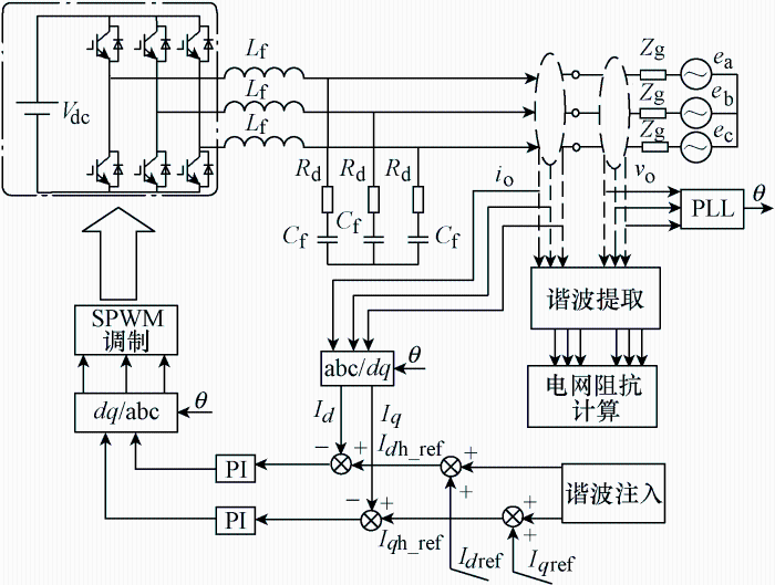
图1为典型的三相并网系统拓扑结构及控制结构。其中, V_{dc}为直流电压; L_{f}和C_{f}构成LC滤波器;R_{d}为阻尼电阻;Z_{g}为电网阻抗;v_{o}为公共耦合点(Point of common coupling, PCC)电压;i_{o}为公共耦合点并网电流。
图1
2.2 基波阻抗辨识原理
图1并网系统中,在给定电流上叠加频率为${{f}_{\text{h}}}$的扰动电流,经过控制环节会在PCC点产生电压和电流响应,采用傅里叶变换提取${{f}_{\text{h}}}$频率下的电压分量和电流分量,进而通过计算得到基波阻抗。
由于电网中含有丰富的背景谐波,在扰动信号频率的选择上,一方面为了尽可能地避开背景谐波的影响,通常选择非特征次谐波注入;另一方面为了能够尽可能地减弱频率变换带来的误差,通常选择距离基波频率较近的谐波,综合考虑本文选择谐波电流扰动的频率为75 Hz。
如图1所示,在并网逆变器控制中,通过在电流参考值上叠加扰动信号,经控制环节在PCC处产生电压响应${{v}_{\text{o}}}\left( t \right)$和电流响应${{i}_{\text{o}}}\left( t \right)$,经离散傅里叶变换提取响应信号中的谐波分量${{v}_{\text{th}}}$和${{i}_{\text{th}}}$,即
利用式(1)计算得到并网点阻抗Zm为
其中,${{v}_{\text{th0}}}$和${{i}_{\text{th0}}}$为未注入扰动时的谐波信号。
从上述分析可以看出,阻抗辨识的核心是非特征次谐波的提取。传统的谐波提取方法有快速傅里叶变换(Fast Fourier transformation, FFT)和离散傅里叶变换(Discrete Fourier transform, DFT),但上述两种方法在计算方面都需要占用大量的内存空间和计算时间。近些年来,有学者提出一种递归离散傅里叶算法(Recursive discrete Fourier transform, RDFT),通过观察DFT和FFT算法可以发现,连续两个采样时刻的样本只是将前一时刻样本的第一个采样值舍弃,在最后加上最新的采样值获得,RDFT算法正是基于上述认识推导而来。
对任意周期信号$x(t)$,若其周期为$T$,设置采样点数为$N$,则其任意时刻的值可以用各次频率分量之和表示为
式中
式中,${{A}_{n}}$、${{B}_{n}}$分别为n次频率分量的正弦、余弦分量的幅值;$k=0$,1,2,3,$\cdots $,$N-1$;采样间隔$\tau =T/N$。
以计算基波为例,对式(4)进行改造可得
其中,${{N}_{\text{c}}}$为新的采样点。
观察式(5)可以发现,当前采样时刻计算A1、B1与上一时刻${{{A}'}_{1}}$、${{{B}'}_{1}}$的计算值存在如下迭代关系
由式(6)可知,在已知前一时刻计算值的基础上,只要通过简单的减法和乘法就可以得到新的值。整个递归计算过程只需要在初始化阶段的一个工频周期内完成周期求和运算,之后就可以按照式(6)递归计算来完成,从而大大减小了计算量。
用DFT和RDFT对同一谐波采样信号进行检测分析,采样点数设为N,提取谐波总数设为N,这两种算法的计算量和响应速度对比见下表。
由上表可知,RDFT在减小运算量方面相比DFT具有较大优势。实际计算过程中,采样频率越高,对应采样点数N越大,RDFT在减小运算量方面优势更加突出。
3 并网系统短路比测量原理
3.1 短路比定义
在多逆变器控制系统中,常用短路比来衡量交流系统的强度。短路比定义为交流电网的短路容量与电力电子设备的接入容量之比,即
式中,${{S}_{\text{ac}}}$为交流电网短路容量;${{S}_{\text{B}}}$为电力电子设备的接入容量。
上级调度部门可以获知每台并网逆变器的接入容量,并且交流电网的短路容量已知,所以很容易得知系统的短路比。但对于单台逆变器,在没有通信的前提下很难直接获得所处并网系统的短路容量,本文提出了一种基于基波阻抗辨识的短路比测量方法。
3.2 基于基波阻抗辨识的短路比测量原理
考虑到多逆变器可以等效成两逆变器系统[9],所以本文以两逆变器系统为例,研究基于基波阻抗辨识的短路比测量原理。
图2为两逆变器并网系统,对于并网逆变器1而言,其自身投入电网的容量已知,记为S1,电网阻抗为${{Z}_{\text{g}}}$,电网的短路容量为${{S}_{\text{ac}}}$。
图2
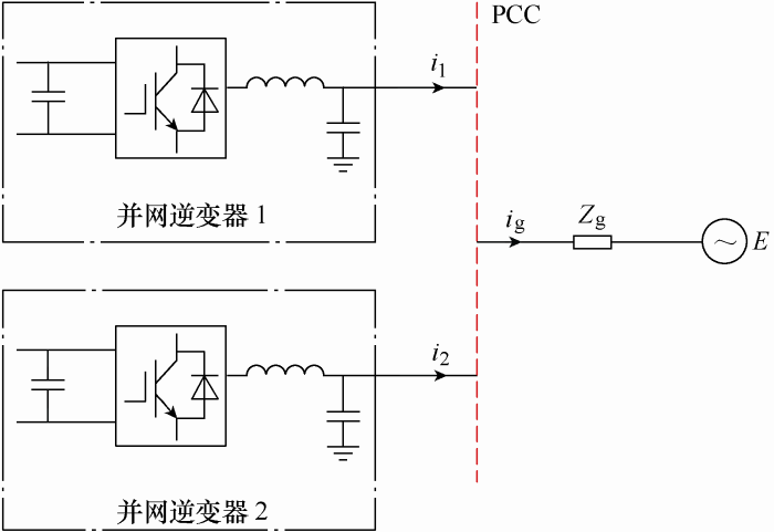
当并网逆变器1正常开机工作时,利用上述所提的阻抗辨识方法,测量此时的基波阻抗为Z1,当并网逆变器2接入后,测得的电网阻抗为Z2,可以得到该并网系统下电力电子设备的投入容量为
式中,${{S}_{\text{B}}}$为电力电子设备的投入容量;${{S}_{2}}$为并网逆变器2的投入容量;$k$为注入扰动与逆变器容量之间的比例关系,工程中一般取5%~10%。
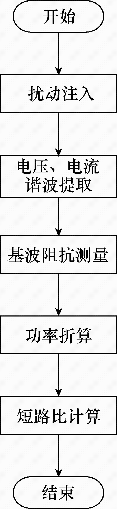
由式(7)、(8)可以计算得到短路比,计算方法为
具体流程如图3所示。
图3
4 仿真和试验
4.1 仿真验证
图4
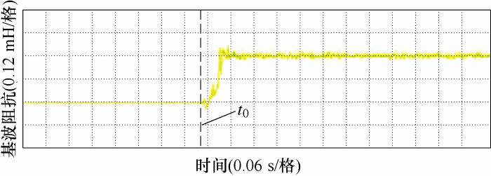
图5
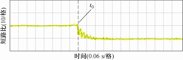
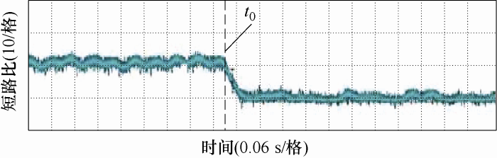
可以发现,在投入2#并网逆变器后基波阻抗增加为原来的2倍,短路比减小为原来的一半。
4.2 试验验证
图6

图7
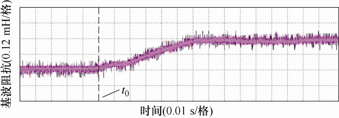
图8
5 结论
本文提出了一种基于基波阻抗辨识的短路比测量方法,并结合Matlab/Simulink仿真和试验,验证了该方法的正确性。结论如下所述。
(1) 采用谐波扰动方案可以精确地检测基波阻抗。
(2) 本文从基波阻抗出发,得出了基波阻抗与并网系统短路比的关系,并提出了一种短路比测量方法,为后续的稳定性判定及自适应控制提供了便利。
参考文献
An optimization strategy of controlled electric vehicle charging considering demand side response and regional wind and photovoltaic
[J].
电网接纳风电能力的评估及应用
[J].
Evaluation and application of wind power integration capacity in power grid
[J].
多个并网逆变器间的交互影响分析
[J].
Analysis on interactive influences among multi grid-connected inverters
[J].
Impedance based stability criterion for grid connected inverters
[J].
DOI:10.1109/TPEL.2011.2136439
URL
Magsci
[本文引用: 1]

Grid-connected inverters are known to become unstable when the grid impedance is high. Existing approaches to analyzing such instability are based on inverter control models that account for the grid impedance and the coupling with other grid-connected inverters. A new method to determine inverter-grid system stability using only the inverter output impedance and the grid impedance is developed in this paper. It will be shown that a grid-connected inverter will remain stable if the ratio between the grid impedance and the inverter output impedance satisfies the Nyquist stability criterion. This new impedance-based stability criterion is a generalization to the existing stability criterion for voltage-source systems, and can be applied to all current-source systems. A single-phase solar inverter is studied to demonstrate the application of the proposed method.
并网逆变器电网阻抗检测技术综述
[J].
Review of grid impedance estimation for gird-connected inverter
[J].
Impact of short-circuit ratio and phase-locked-loop parameters on the small-signal behavior of a VSC-HVDC converter
[J].
DOI:10.1109/TPWRD.2014.2330518
URL
Magsci
[本文引用: 1]
The impact of phase-locked loop (PLL) parameters on the dynamic and steady-state behavior of a voltage-source converter (VSC) in an HVDC transmission system is determined as a function of the system strength [parameterized by the short-circuit ratio (SCR)]. This is achieved by using a linearized small-signal model of the converter system and its controls. The model is validated via electromagnetic transients simulation of the fully detailed large signal model. An interesting result from this study is that the maximum power transfer capability of the VSC-HVDC converter is affected by the PLL gains, and that the theoretical limit (obtained from static voltage stability analysis) is approachable as the PLL gains become very small. This paper shows that gains of the PLL, particularly at low SCRs, greatly affect the operation of the VSC-HVDC converter and that operation at low SCRs approaching 1.3 is very difficult.
多馈入直流系统广义短路比:定义与理论分析
[J].
Generalized short circuit ratio for multi-infeed DC systems:definition and theoretical analysis
[J].
MIMO identification techniques for rapid impedance-based stability assessment of three phase systems in dq domain
[J].
光伏并网多逆变器并联建模及谐振分析
[J].
DOI:10.13334/j.0258-8013.pcsee.2014.03.003
URL
Magsci
[本文引用: 1]
针对光伏并网发电系统中多逆变器并联谐振问题, 首先, 建立包括电流控制、电压前馈和脉宽调制(pulse width modulation, PWM)谐波特性的单台逆变器小信号电路模型, 并扩展成多逆变器并联小信号模型, 提出基于2台逆变器和同类激励源合并的多逆变器并联系统小信号模型简化等效方法, 分析多逆变器的基本谐振特性, 并得出谐振与各逆变器控制和载波同步性有关的结论。最后, 通过相关的实验研究, 验证了所提出的多逆变器简化等效模型和理论分析的正确性。
Modeling and resonance analysis of multi-paralleled grid-tied inverters in PV systems
[J].
DOI:10.13334/j.0258-8013.pcsee.2014.03.003
URL
Magsci
[本文引用: 1]
针对光伏并网发电系统中多逆变器并联谐振问题, 首先, 建立包括电流控制、电压前馈和脉宽调制(pulse width modulation, PWM)谐波特性的单台逆变器小信号电路模型, 并扩展成多逆变器并联小信号模型, 提出基于2台逆变器和同类激励源合并的多逆变器并联系统小信号模型简化等效方法, 分析多逆变器的基本谐振特性, 并得出谐振与各逆变器控制和载波同步性有关的结论。最后, 通过相关的实验研究, 验证了所提出的多逆变器简化等效模型和理论分析的正确性。
