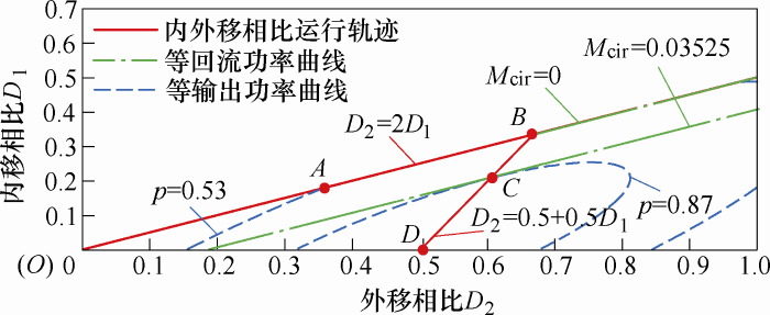
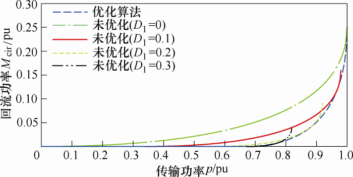
A minimum reactive power control strategy based on the dual-phase-shift control with bidirectional inner phase shifts(DPS-BIPS) modulation strategy is proposed to solve the low operating efficiency of the dual active bridge DC-DC converter caused by the reactive power. The control strategy achieves a minimum reactive power operation over the full power range by seeking an optimal combination of shifts. The working principle of DPS-BIPS is introduced,and its mathematical model of transmission power and reactive power is established. The minimum reactive power control strategy is proposed. Finally, the effectiveness of the optimization control algorithm is verified by experiment.
Keywords:Dual active bridge DC-DC converter
;
DPS-BIPS
;
reactive power
;
optimization control
GAO Shuai. Minimum Reactive Power Control Strategy for Dual Active Bridge DC-DC Converter. Journal of Electrical Engineering[J], 2019, 14(2): 24-29 doi:10.11985/2019.02.005
1 引言
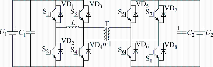
双有源桥(Dual Active Bridge,DAB)DC-DC变换器由于其较高的功率密度、双向的能量传递以及易于实现软开关等特点,在分布式发电、电动汽车、智能电网中有着广泛的应用[1,2,3,4]。DAB变换器采用传统的单移相(Single-Phase-Shift,SPS)控制方式时,换流过程中存在一次侧H桥的交流输出电压和电感电流方向相反的阶段,此时移相电感中的能量流回输入电源侧,这部分功率称为回流功率。回流功率直接影响着变换器的传输效率,因此,如何实现最小回流功率运行受到研究人员越来越多的关注。
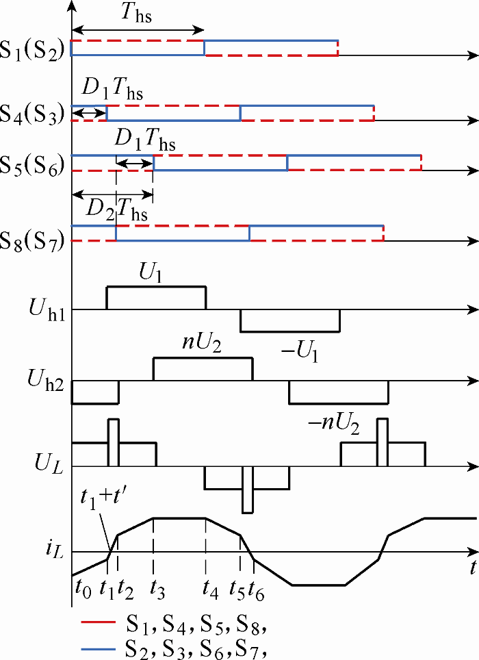
为克服SPS控制时因自由度少而无法实现回流功率优化的缺点,扩展移相[5,6](Extended-Phase-Shift,EPS)、双重移相[7](Dual-Phase-Shift,DPS),三重移相[8,9](Triple-Phase-Shift,TPS)等调制方法相继提出,并且针对不同的调制方法都有相应的最小回流功率的优化控制策略。但是,EPS调制时一、二次侧H桥电压转换状态不同,实现功率双向控制较为复杂[3];DPS调制在恒功率传输时,外移相比微小的变化会产生内移相比较大的变化,产生严重的浪涌电流,导致功率传输不稳定[10];TPS调制的自由度最多,控制系统设计复杂。文献[10]提出的双重双向内移相(Dual-Phase-Shift control with bidirectional inner phase shifts,DPS-BIPS)调制方法,抑制了DPS调制时在恒功率传输中产生的浪涌电流,使得功率传输更加稳定;相比EPS、TPS调制,功率双向控制系统设计简单,但如何实现DPS-BIPS调制时最小回流功率运行还有待研究。因此,现有方案虽然能实现最小回流功率控制,但增加了控制系统的复杂性,有些方案甚至造成功率传输的不稳定。
High-frequency-link (HFL) power conversion systems (PCSs) are attracting more and more attentions in academia and industry for high power density, reduced weight, and low noise without compromising efficiency, cost, and reliability. In HFL PCSs, dual-active-bridge (DAB) isolated bidirectional dc-dc converter (IBDC) serves as the core circuit. This paper gives an overview of DAB-IBDC for HFL PCSs. First, the research necessity and development history are introduced. Second, the research subjects about basic characterization, control strategy, soft-switching solution and variant, as well as hardware design and optimization are reviewed and analyzed. On this basis, several typical application schemes of DAB-IBDC for HPL PCSs are presented in a worldwide scope. Finally, design recommendations and future trends are presented. As the core circuit of HFL PCSs, DAB-IBDC has wide prospects. The large-scale practical application of DAB-IBDC for HFL PCSs is expected with the recent advances in solid-state semiconductors, magnetic and capacitive materials, and microelectronic technologies.
A novel naturally clamped zero-current commutated soft-switching bidirectional current-fed full-bridge isolated dc/dc converter is proposed. This proposed secondary-modulation technique naturally clamps the voltage across the primary-side devices with zero-current commutation, eliminating the necessity for active-clamp circuit or passive snubbers. Switching losses are reduced significantly owing to zero-current switching of primary-side devices and zero-voltage switching of secondary-side devices. Soft switching and voltage clamping are inherent and load independent. The voltage across primary-side devices is independent of duty cycle with varying input voltage and output power and clamped at rather low reflected output voltage, enabling the use of semiconductor devices of low voltage rating. These merits make the converter promising for fuel cell vehicles application, front-end dc/dc power conversion for fuel cell inverters, and energy storage. Steady-state operation, analysis, design, simulation results using PSIM 9.0.4, and experimental results are presented.
An efficiency-optimized modulation scheme and design method are developed for an existing hardware prototype of a bidirectional dual active bridge (DAB) dc/dc converter. The DAB being considered is used for an automotive application and is made up of a high-voltage port with port voltage V-1, 240 V <= V1 <= 450 V, and a low-voltage port with port voltage V-2, 11 V <= V-2 <= 16 V; the rated output power is 2 kW. A much increased converter efficiency is achieved with the methods detailed in this paper: The average efficiency, calculated for different voltages V-1 and V-2, different power levels, and both directions of power transfer, rises from 89.6% (conventional phase shift modulation) to 93.5% (proposed modulation scheme). Measured efficiency values, obtained from the DAB hardware prototype, are used to verify the theoretical results.
LiuX, Zhu ZQ, Stone DA, et al.
Novel dual-phase-shift control with bidirectional inner phase shifts for a dual- active-bridge converter having low surge current and stable power control
[J]. IEEE Transactions on Power Electronics, 2017,32(5):4095-4106.
... 双有源桥(Dual Active Bridge,DAB)DC-DC变换器由于其较高的功率密度、双向的能量传递以及易于实现软开关等特点,在分布式发电、电动汽车、智能电网中有着广泛的应用[1,2,3,4].DAB变换器采用传统的单移相(Single-Phase-Shift,SPS)控制方式时,换流过程中存在一次侧H桥的交流输出电压和电感电流方向相反的阶段,此时移相电感中的能量流回输入电源侧,这部分功率称为回流功率.回流功率直接影响着变换器的传输效率,因此,如何实现最小回流功率运行受到研究人员越来越多的关注. ...
智能直流配电网研究综述
1
2013
... 双有源桥(Dual Active Bridge,DAB)DC-DC变换器由于其较高的功率密度、双向的能量传递以及易于实现软开关等特点,在分布式发电、电动汽车、智能电网中有着广泛的应用[1,2,3,4].DAB变换器采用传统的单移相(Single-Phase-Shift,SPS)控制方式时,换流过程中存在一次侧H桥的交流输出电压和电感电流方向相反的阶段,此时移相电感中的能量流回输入电源侧,这部分功率称为回流功率.回流功率直接影响着变换器的传输效率,因此,如何实现最小回流功率运行受到研究人员越来越多的关注. ...
Dual active bridge based battery charger for plug-in hybrid electric vehicle with charging current containing low frequency ripple
1
2015
... 双有源桥(Dual Active Bridge,DAB)DC-DC变换器由于其较高的功率密度、双向的能量传递以及易于实现软开关等特点,在分布式发电、电动汽车、智能电网中有着广泛的应用[1,2,3,4].DAB变换器采用传统的单移相(Single-Phase-Shift,SPS)控制方式时,换流过程中存在一次侧H桥的交流输出电压和电感电流方向相反的阶段,此时移相电感中的能量流回输入电源侧,这部分功率称为回流功率.回流功率直接影响着变换器的传输效率,因此,如何实现最小回流功率运行受到研究人员越来越多的关注. ...
Overview of dual-active-bridge isolated bidirectional DC-DC converter for high-frequency-link power-conversion system
2
2014
... 双有源桥(Dual Active Bridge,DAB)DC-DC变换器由于其较高的功率密度、双向的能量传递以及易于实现软开关等特点,在分布式发电、电动汽车、智能电网中有着广泛的应用[1,2,3,4].DAB变换器采用传统的单移相(Single-Phase-Shift,SPS)控制方式时,换流过程中存在一次侧H桥的交流输出电压和电感电流方向相反的阶段,此时移相电感中的能量流回输入电源侧,这部分功率称为回流功率.回流功率直接影响着变换器的传输效率,因此,如何实现最小回流功率运行受到研究人员越来越多的关注. ...
... 为克服SPS控制时因自由度少而无法实现回流功率优化的缺点,扩展移相[5,6](Extended-Phase-Shift,EPS)、双重移相[7](Dual-Phase-Shift,DPS),三重移相[8,9](Triple-Phase-Shift,TPS)等调制方法相继提出,并且针对不同的调制方法都有相应的最小回流功率的优化控制策略.但是,EPS调制时一、二次侧H桥电压转换状态不同,实现功率双向控制较为复杂[3];DPS调制在恒功率传输时,外移相比微小的变化会产生内移相比较大的变化,产生严重的浪涌电流,导致功率传输不稳定[10];TPS调制的自由度最多,控制系统设计复杂.文献[10]提出的双重双向内移相(Dual-Phase-Shift control with bidirectional inner phase shifts,DPS-BIPS)调制方法,抑制了DPS调制时在恒功率传输中产生的浪涌电流,使得功率传输更加稳定;相比EPS、TPS调制,功率双向控制系统设计简单,但如何实现DPS-BIPS调制时最小回流功率运行还有待研究.因此,现有方案虽然能实现最小回流功率控制,但增加了控制系统的复杂性,有些方案甚至造成功率传输的不稳定. ...
... 双有源桥(Dual Active Bridge,DAB)DC-DC变换器由于其较高的功率密度、双向的能量传递以及易于实现软开关等特点,在分布式发电、电动汽车、智能电网中有着广泛的应用[1,2,3,4].DAB变换器采用传统的单移相(Single-Phase-Shift,SPS)控制方式时,换流过程中存在一次侧H桥的交流输出电压和电感电流方向相反的阶段,此时移相电感中的能量流回输入电源侧,这部分功率称为回流功率.回流功率直接影响着变换器的传输效率,因此,如何实现最小回流功率运行受到研究人员越来越多的关注. ...
双重移相控制的双向全桥DC-DC 变换器及其功率回流特性分析
1
2012
... 为克服SPS控制时因自由度少而无法实现回流功率优化的缺点,扩展移相[5,6](Extended-Phase-Shift,EPS)、双重移相[7](Dual-Phase-Shift,DPS),三重移相[8,9](Triple-Phase-Shift,TPS)等调制方法相继提出,并且针对不同的调制方法都有相应的最小回流功率的优化控制策略.但是,EPS调制时一、二次侧H桥电压转换状态不同,实现功率双向控制较为复杂[3];DPS调制在恒功率传输时,外移相比微小的变化会产生内移相比较大的变化,产生严重的浪涌电流,导致功率传输不稳定[10];TPS调制的自由度最多,控制系统设计复杂.文献[10]提出的双重双向内移相(Dual-Phase-Shift control with bidirectional inner phase shifts,DPS-BIPS)调制方法,抑制了DPS调制时在恒功率传输中产生的浪涌电流,使得功率传输更加稳定;相比EPS、TPS调制,功率双向控制系统设计简单,但如何实现DPS-BIPS调制时最小回流功率运行还有待研究.因此,现有方案虽然能实现最小回流功率控制,但增加了控制系统的复杂性,有些方案甚至造成功率传输的不稳定. ...
基于双重移相控制的双向全桥DC-DC变换器动态建模与最小回流功率控制
1
2014
... 为克服SPS控制时因自由度少而无法实现回流功率优化的缺点,扩展移相[5,6](Extended-Phase-Shift,EPS)、双重移相[7](Dual-Phase-Shift,DPS),三重移相[8,9](Triple-Phase-Shift,TPS)等调制方法相继提出,并且针对不同的调制方法都有相应的最小回流功率的优化控制策略.但是,EPS调制时一、二次侧H桥电压转换状态不同,实现功率双向控制较为复杂[3];DPS调制在恒功率传输时,外移相比微小的变化会产生内移相比较大的变化,产生严重的浪涌电流,导致功率传输不稳定[10];TPS调制的自由度最多,控制系统设计复杂.文献[10]提出的双重双向内移相(Dual-Phase-Shift control with bidirectional inner phase shifts,DPS-BIPS)调制方法,抑制了DPS调制时在恒功率传输中产生的浪涌电流,使得功率传输更加稳定;相比EPS、TPS调制,功率双向控制系统设计简单,但如何实现DPS-BIPS调制时最小回流功率运行还有待研究.因此,现有方案虽然能实现最小回流功率控制,但增加了控制系统的复杂性,有些方案甚至造成功率传输的不稳定. ...
隔离型双向直流变换器的最小回流功率移相控制方法
1
2017
... 为克服SPS控制时因自由度少而无法实现回流功率优化的缺点,扩展移相[5,6](Extended-Phase-Shift,EPS)、双重移相[7](Dual-Phase-Shift,DPS),三重移相[8,9](Triple-Phase-Shift,TPS)等调制方法相继提出,并且针对不同的调制方法都有相应的最小回流功率的优化控制策略.但是,EPS调制时一、二次侧H桥电压转换状态不同,实现功率双向控制较为复杂[3];DPS调制在恒功率传输时,外移相比微小的变化会产生内移相比较大的变化,产生严重的浪涌电流,导致功率传输不稳定[10];TPS调制的自由度最多,控制系统设计复杂.文献[10]提出的双重双向内移相(Dual-Phase-Shift control with bidirectional inner phase shifts,DPS-BIPS)调制方法,抑制了DPS调制时在恒功率传输中产生的浪涌电流,使得功率传输更加稳定;相比EPS、TPS调制,功率双向控制系统设计简单,但如何实现DPS-BIPS调制时最小回流功率运行还有待研究.因此,现有方案虽然能实现最小回流功率控制,但增加了控制系统的复杂性,有些方案甚至造成功率传输的不稳定. ...
Accurate small-signal model for the digital control of an automotive bidirectional dual active bridge
1
2009
... 为克服SPS控制时因自由度少而无法实现回流功率优化的缺点,扩展移相[5,6](Extended-Phase-Shift,EPS)、双重移相[7](Dual-Phase-Shift,DPS),三重移相[8,9](Triple-Phase-Shift,TPS)等调制方法相继提出,并且针对不同的调制方法都有相应的最小回流功率的优化控制策略.但是,EPS调制时一、二次侧H桥电压转换状态不同,实现功率双向控制较为复杂[3];DPS调制在恒功率传输时,外移相比微小的变化会产生内移相比较大的变化,产生严重的浪涌电流,导致功率传输不稳定[10];TPS调制的自由度最多,控制系统设计复杂.文献[10]提出的双重双向内移相(Dual-Phase-Shift control with bidirectional inner phase shifts,DPS-BIPS)调制方法,抑制了DPS调制时在恒功率传输中产生的浪涌电流,使得功率传输更加稳定;相比EPS、TPS调制,功率双向控制系统设计简单,但如何实现DPS-BIPS调制时最小回流功率运行还有待研究.因此,现有方案虽然能实现最小回流功率控制,但增加了控制系统的复杂性,有些方案甚至造成功率传输的不稳定. ...
Efficiency-optimized high current dual active bridge converter for automotive applications
1
2012
... 为克服SPS控制时因自由度少而无法实现回流功率优化的缺点,扩展移相[5,6](Extended-Phase-Shift,EPS)、双重移相[7](Dual-Phase-Shift,DPS),三重移相[8,9](Triple-Phase-Shift,TPS)等调制方法相继提出,并且针对不同的调制方法都有相应的最小回流功率的优化控制策略.但是,EPS调制时一、二次侧H桥电压转换状态不同,实现功率双向控制较为复杂[3];DPS调制在恒功率传输时,外移相比微小的变化会产生内移相比较大的变化,产生严重的浪涌电流,导致功率传输不稳定[10];TPS调制的自由度最多,控制系统设计复杂.文献[10]提出的双重双向内移相(Dual-Phase-Shift control with bidirectional inner phase shifts,DPS-BIPS)调制方法,抑制了DPS调制时在恒功率传输中产生的浪涌电流,使得功率传输更加稳定;相比EPS、TPS调制,功率双向控制系统设计简单,但如何实现DPS-BIPS调制时最小回流功率运行还有待研究.因此,现有方案虽然能实现最小回流功率控制,但增加了控制系统的复杂性,有些方案甚至造成功率传输的不稳定. ...
Novel dual-phase-shift control with bidirectional inner phase shifts for a dual- active-bridge converter having low surge current and stable power control
2
2017
... 为克服SPS控制时因自由度少而无法实现回流功率优化的缺点,扩展移相[5,6](Extended-Phase-Shift,EPS)、双重移相[7](Dual-Phase-Shift,DPS),三重移相[8,9](Triple-Phase-Shift,TPS)等调制方法相继提出,并且针对不同的调制方法都有相应的最小回流功率的优化控制策略.但是,EPS调制时一、二次侧H桥电压转换状态不同,实现功率双向控制较为复杂[3];DPS调制在恒功率传输时,外移相比微小的变化会产生内移相比较大的变化,产生严重的浪涌电流,导致功率传输不稳定[10];TPS调制的自由度最多,控制系统设计复杂.文献[10]提出的双重双向内移相(Dual-Phase-Shift control with bidirectional inner phase shifts,DPS-BIPS)调制方法,抑制了DPS调制时在恒功率传输中产生的浪涌电流,使得功率传输更加稳定;相比EPS、TPS调制,功率双向控制系统设计简单,但如何实现DPS-BIPS调制时最小回流功率运行还有待研究.因此,现有方案虽然能实现最小回流功率控制,但增加了控制系统的复杂性,有些方案甚至造成功率传输的不稳定. ...
... ;TPS调制的自由度最多,控制系统设计复杂.文献[10]提出的双重双向内移相(Dual-Phase-Shift control with bidirectional inner phase shifts,DPS-BIPS)调制方法,抑制了DPS调制时在恒功率传输中产生的浪涌电流,使得功率传输更加稳定;相比EPS、TPS调制,功率双向控制系统设计简单,但如何实现DPS-BIPS调制时最小回流功率运行还有待研究.因此,现有方案虽然能实现最小回流功率控制,但增加了控制系统的复杂性,有些方案甚至造成功率传输的不稳定. ...


