


1 引言
无刷直流电动机具有效率高、体积小、可靠性高、特性好、调速方便、结构简单等优点,已广泛应用于航空、航天、航海等领域以及各民用工业领域。无刷直流电动机转子结构形式十分灵活,根据永磁体在转子中放置的位置,可以分为内嵌式和表贴式。不同分法又可以相互组合,因此可以构成许多各有特色的转子磁路结构[1]。无刷直流电动机的磁场分布复杂,而且永磁体随温度的升高将出现退磁现象,直接影响磁场的大小及分布,并使得电机的性能产生波动[2]。因此,转子磁路结构不同,损耗大小和发热程度对无刷直流电动机的性能、工艺和适用场合有很大影响,这是无刷直流电动机设计的一个重要环节。内嵌式无刷直流电动机相对于表贴式转子结构形式更灵活,设计参数多,是目前国内外研究的热点[3]。
2 电机结构及基本参数
图1
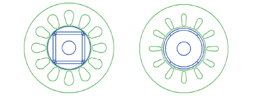
表1 电机设计基本参数
Tab.1
| 参 数 | 内嵌式 | 表贴式 |
|---|---|---|
| 额定功率/kW | 10 | 10 |
| 额定电压/V | 500 | 500 |
| 极数 | 4 | 4 |
| 定子槽数 | 12 | 12 |
| 轴向长度/mm | 78 | 78 |
| 永磁体材料 | NdFeB | NdFeB |
| 额定转速/(r/min) | 10 000 | 10 00 |
| 额定电流/A | 20 | 20 |
| 气隙大小/mm | 1.5 | 1.75 |
| 定子外径/mm | 160 | 160 |
| 定子内径/mm | 80 | 80 |
| 转子外径/mm | 77 | 74.5 |
| 转子内径/mm | 25 | 25 |
3 电机分析
3.1 转子应力的有限元分析
由于本文设计的电机转速为10 000r/min,比一般电机要大,其转子表面的永磁体承受很大的离心力,因此利用有限元法对永磁体转子应力进行了分析。转速为10 000r/min、运行温度为75℃的三台电机2D转子应力分布如图2所示。
图2
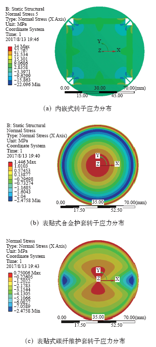
由图2可知,当转速为10 000r/min,运行温度较高(75℃)时,转子等效应力分别为34MPa、1.446MPa和0.750 06MPa,符合对电机转子的机械强度要求。
3.2 损耗分析
图3
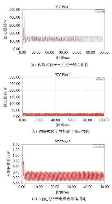
图4
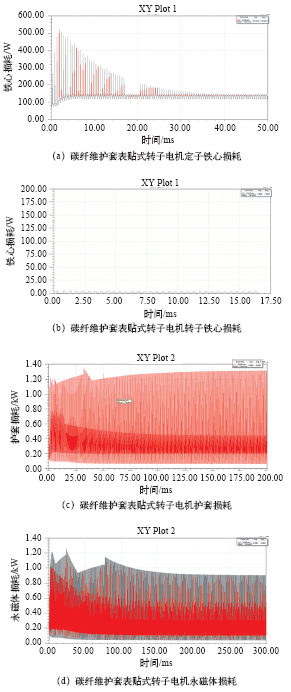
图4
碳纤维护套表贴式转子电机各部分损耗曲线
Fig.4
Loss curves of the alloy sheathed surface-mounted rotor motor
图5
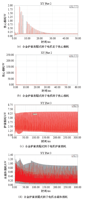
图5
合金护套表贴式转子结构电机各部分损耗曲线
Fig.5
Loss curves of carbon fiber sheathed surface-mounted rotor motor
本文利用二维有限元法、RMxprt和Ansoft进行电机分析,分别计算得到了三台电机定子的铁心损耗、转子铁心损耗、永磁体涡流损耗和电枢铜耗。由图可知,在额定负载下,内嵌式转子定子铁心损耗为184.1W,转子铁心损耗为19.585W,永磁体损耗为62.265 W,电枢铜耗为100.694W,总损耗为366.641W。合金护套表贴式转子电机定子铁心损耗为137.3W,转子铁心损耗为1.752 3W,永磁体损耗为84.525W,电枢铜耗为87.316 1W,护套损耗为436.1W,总损耗为746.993 4W。碳纤维护套表贴式转子电机定子铁心损耗为133.4W,转子铁心损耗为1.903 2W,永磁体损耗为62.265W,电枢铜耗为87.316 1W,护套损耗为271.2W,总损耗为556.084 3W。可知在额定负载下,内嵌式电机损耗最小,表贴式电机损耗比较大,其中合金护套电机损耗最大。
4 温度场分析
高速电机体积小,功率密度大,同时单位体积损耗也大。电机在工作时发热严重,散热也比较困难,因此温升较高。而永磁体材料的性能受温度影响较大,温升较高可能会导致永磁体发生不可逆退磁进而损坏电机[7],因此对温升进行分析十分重要。
无刷直流电动机内部电磁场分布非常复杂,各部分发热情况不均匀,散热条件也相差悬殊,热源之间又存在一定的热交换,所以该类电机内部的热场分析存在一定困难。电机的热量是由电机各个部分的损耗引起的,这些热量一般通过热传导作用,由发热体的内部传递到发热体表面,然后再通过热对流和热辐射的形式将热量发散到周围介质中[8]。
根据电机内的流体流动和传热情况给出了温度场相应的边界条件,即
(1)风路采用流–固耦合,给定相应入口温度25℃、风速15m/s的风冷和出口压力。
(2)对定子槽内部进行了等效绝缘处理。
(3)电机定子、绕组、护套、永磁体加载相应的温度,作为电机热源。
(4)电机转子部分设定转速,模拟实际电机旋转。
两种转子结构电机求解域模型如图6所示。
图6
图6
两种转子结构电机求解域模型
Fig.6
The solution domain models of two rotor structure motor
本文采用的NdFeB永磁体材料所能承受的最高温度为180℃,当永磁体温度高于该温度时,永磁体会发生不可逆退磁,严重影响了电机的可靠运行。本文采用定转子风冷,进口端温度为25℃、风速为15m/s、压强大约为300Pa的风冷,以使永磁体温度保持在安全范围内。
表2为三台电机的各部件最高温度。从表中可以看出,三台电机在相同功率转速下,内嵌式转子无刷直流电机温度比表贴式温度低,表贴式合金护套转子比碳纤维护套转子温度高。
Tab.2 Maximum temperature of each part of motor(单位:K)
| 部件 | 内嵌式 | 合金护套 | 碳纤维护套 |
|---|---|---|---|
| 转轴 | 315 | 579 | 538 |
| 转子铁心 | 315 | 579 | 538 |
| 永磁体 | 254 | 579 | 538 |
| 护套 | 579 | 538 | |
| 绕组 | 217 | 398 | 398 |
| 定子铁心 | 247 | 416 | 402 |
| 机壳 | 231 | 389 | 385 |
5 结论
本文设计了一台10kW、10 000r/min的永磁高速直流电机,并分别设计了内嵌式和表贴式两种不同转子结构,针对表贴式转子结构分析了合金护套和碳纤维护套。通过Ansoft有限元分析,分别得到三台电机各部件损耗曲线参数,通过ANSYS静力分析可知该设计符合电机设计。利用ANSYS软件下的CFX模块建立了两种转子结构的电机三维求解域模型,根据电机内流体流动和传热情况给出了温度场计算相应的边界条件,计算出三台电机的温度场分布。
通过图表参数对比可知在该参数设计下,内嵌式永磁同步无刷直流高速电机损耗更小,表贴式损耗较大,发热较大,容易引起扫膛,嵌入式结构损耗较小,不存在局部发热现象,但在磁钢端部存在明显漏磁,引起环流使电流波形发生畸变[9]。两种转子结构各有利弊,设计中应根据电机的应用背景及技术指标进行选用。
参考文献
Study on design feature and related technology of high speed electrical machines
[J].
High-speed electrical machines: technologies, trends, and developments
[J].
DOI:10.1109/TIE.2013.2286777
URL
[本文引用: 1]

This paper reviews the current technologies used in high-speed electrical machines through an extensive survey of different topologies developed and built in the industry and academia for several applications. Developments in materials and components, including electrical steels and copper alloys, are discussed, and their impact on the machines' operating physical boundaries is investigated. The main application areas pulling the development of high-speed machines are also reviewed to better understand the typical performance requirements.
Power limits of high-speed permanent-magnet electrical machines for compressor applications
[J].
DOI:10.1109/TEC.2010.2089459
URL
[本文引用: 1]
The maximum-power limits for high-speed permanent-magnet (PM) electrical machines for air compressor applications are determined in the speed range 20 000-100 000 r/min. For this purpose, five PM machines are designed and the electromagnetic, thermal, and mechanical designs of each machine are simultaneously performed. The critical values of the thermal and mechanical constraints are considered in order to obtain the maximum powers of the electrical machines. The electromagnetic losses generated in the machine are the output parameters of the electromagnetic design and input parameters for the thermal design. The thermal design is performed using a multiphysics method, which couples computational-fluid-dynamics equations with heat-transfer equations. The mechanical design considers the retention of the rotor elements against the huge centrifugal forces that arise during the high-speed operation and also the rotordynamics properties of the rotor. The reliability of these design techniques is experimentally validated in the paper. The obtained maximum-power limit defines the speed-power region, in which the high-speed PM electrical machines intended for compressor applications can have a safe operation.
Design and analysis of electromagnetic properties for high speed PM generator
[J].
无刷直流电动机电磁场-热场耦合分析
[J].
DOI:10.4142/jvs.2019.20.e73
URL
PMID:31775199
[本文引用: 1]
Chronic kidney disease is considered to be most common in geriatric domestic cats. It has been reported that the feline viral rhinotracheitis, calicivirus, and panleukopenia (FVRCP) vaccine prepared from the Crandell-Rees feline kidney (CRFK) cell line can induce cross-reactions of antibodies with feline kidney tissues. As an anti-cat kidney antibody was not available commercially for this study of autoantibody in cats, the purpose of this study was to produce anti-cat kidney antibody in rabbits for further study of autoantibody in cats after FVRCP vaccination. Kidney proteins from cadaveric cats were extracted and immunized into rabbits using Montanide as the adjuvant. Based on enzyme-linked immunosorbent assay measurement, all immunized rabbits produced high levels of anti-cat kidney antibodies and some began to produce antibodies as early as 2 weeks after immunization. Immunofluorescence staining of rabbit sera showed kidney-bound antibodies in glomerulus, Bowman's capsule, apical surface of the proximal convoluted tubule, peritubular surface, and interstitial cells. Western blot analysis of cat kidney proteins revealed molecular weights (M.W.) of 72, 55, 47, and 31 kDa, while binding to the CRFK cell proteins was observed at M.W. of 43 and 26 kDa. The antibody that recognized the 47 kDa protein was similarly detected in cats with autoantibody presence after FVRCP vaccination. The kidney-bound antibody profile at different time points and its patterns in rabbits could be used as a model for the study of autoantibody to cat kidney in feline chronic kidney diseases.
Electromagnetic field-thermal field coupling analysis of brushless DC motor
[J].
DOI:10.4142/jvs.2019.20.e73
URL
PMID:31775199
[本文引用: 1]
Chronic kidney disease is considered to be most common in geriatric domestic cats. It has been reported that the feline viral rhinotracheitis, calicivirus, and panleukopenia (FVRCP) vaccine prepared from the Crandell-Rees feline kidney (CRFK) cell line can induce cross-reactions of antibodies with feline kidney tissues. As an anti-cat kidney antibody was not available commercially for this study of autoantibody in cats, the purpose of this study was to produce anti-cat kidney antibody in rabbits for further study of autoantibody in cats after FVRCP vaccination. Kidney proteins from cadaveric cats were extracted and immunized into rabbits using Montanide as the adjuvant. Based on enzyme-linked immunosorbent assay measurement, all immunized rabbits produced high levels of anti-cat kidney antibodies and some began to produce antibodies as early as 2 weeks after immunization. Immunofluorescence staining of rabbit sera showed kidney-bound antibodies in glomerulus, Bowman's capsule, apical surface of the proximal convoluted tubule, peritubular surface, and interstitial cells. Western blot analysis of cat kidney proteins revealed molecular weights (M.W.) of 72, 55, 47, and 31 kDa, while binding to the CRFK cell proteins was observed at M.W. of 43 and 26 kDa. The antibody that recognized the 47 kDa protein was similarly detected in cats with autoantibody presence after FVRCP vaccination. The kidney-bound antibody profile at different time points and its patterns in rabbits could be used as a model for the study of autoantibody to cat kidney in feline chronic kidney diseases.
Improved analytical modeling of rotor eddy current loss in brushless machines equipped with surface-mounted permanent magnets
[J].DOI:10.1049/ip-epa:20040546 URL [本文引用: 1]
永磁内嵌式无刷直流电机铁耗的分析和计算
[J].
Analysis and calculation of iron loss of permanent magnet embedded brushless DC motor
[J].
Novel rotor design for interior permanent magnet brushless machines: initial investigation
[C].
A design approach to reduce rotor losses in high-speed permanent magnet machine for turbo-compressor
[J].DOI:10.1109/TMAG.2006.879086 URL [本文引用: 1]
