


1 引言
通过在主动磁悬浮轴承系统中引入错误识别和诊断系统可以在一定程度上提高主动磁悬浮轴承的可靠性。错误识别和诊断(Fault Detection and Diagnosis,FDD)系统的主要任务是实时检测主动磁悬浮轴承的各个子系统的功能,如果某个子系统的功能不正常,则错误识别和诊断系统将自动识别出故障单元并对故障单元进行替换,因此错误识别和诊断系统要求系统具有一定的功能冗余度。FDD系统的关键就在于故障的诊断与识别。
主动磁悬浮轴承系统通常采用差动式位移传感器以提高位移检测的性能。差动式位移传感器在每个自由度上安装有两个位移传感器(本文分别称为传感器1和传感器2)同时检测转子的位移。针对采用差动式位移传感器的主动磁悬浮轴承系统,介绍了一种位移传感器故障的识别方法。该方法可以通过分析两路位移信号和控制器的输出信号来检测传感器的故障并识别出故障传感器。
2 差动式位移传感器输出信号与故障信号及干扰力的关系
图1为采用差动式电涡流位移传感器的主动磁悬浮轴承单自由度系统结构框图。图中,C(s)为控制器;Ki为磁悬浮轴承的电流刚度系数;G(s)为转子模型;Ks1和Ks2分别为传感器1和传感器2的增益;r为参考输入;f为转子所受的干扰力;d1、d2分别为施加在传感器1和传感器2上的干扰信号,分别用来模拟传感器1和传感器2的故障;V1、V2分别为传感器1和传感器2的输出信号;uc为控制器的输出信号。
由图1可得两个传感器的输出信号和故障信号、干扰力之间的关系为
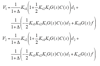
其中, 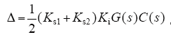
图1
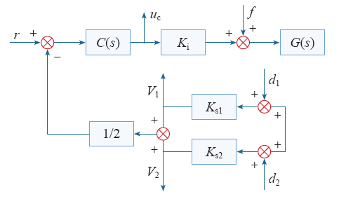
图1
差动位移传感器的主动磁悬浮轴承系统结构框图
Fig.1
Structure diagram of active magnetic suspension bearing system with differential displacement sensor
3 传感器故障检测原理
传感器故障的形式多种多样。本系统中的传感器主要有两大类故障形式,分别为非完全型故障和完全型故障。其中非完全型故障主要包括漂移偏差故障和固定偏差故障,主要是由偏置电流或偏置电压以及工作传感器发生温漂造成;而完全型故障主要包括开路故障和短路故障,主要是由于传感器信号线断路以及传感器硬件电路中芯片管脚未连接上或信号线短接造成的。
根据式(1),可以推导出两个传感器输出信号的差值为
假设两个传感器的特性完全一致,即有
$K_{s1} = K_{s2} = K_{s}$
则式(2)可以简化为
由式(3)可知,当两个传感器的特性完全相同时,两个位移传感器输出信号的差值仅与传感器故障信号有关。可利用这个特征来检测传感器的故障,即只要Vd不为零,就表示某个传感器有故障。实际应用中两个传感器的特性不可能完全一致,因此定义一个允许的误差阈值Vtol,如果两个传感器的差值信号满足如下关系式

则认为传感器没有发生故障,否则判定传感器出现故障。
4 故障传感器的识别
由式(3)可知,两个传感器中任一个传感器发生故障都会导致Vd发生变化,因此通过Vd尽管可以发现传感器有故障但却无法确定哪个传感器有故障,必须通过检测其他信号来识别故障传感器。
本文将通过分析各信号之间的关系来对出现故障的传感器进行识别。根据图1的系统框图可以推导出控制器的输出电压和传感器干扰信号及转子干扰力之间的关系为
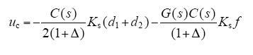
由式(4)可知,控制器的输出信号包含两部分:一部分和传感器的故障信号有关;一部分和转子的干扰力有关。令
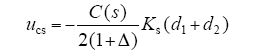
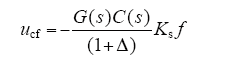
则式(4)可简化为
$u_{c}=u_{cs}+u_{cf}$
当传感器1失效,即只有干扰信号d1时,则
将式(7)代入式(5),可得
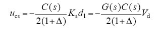
当传感器2失效,即只有干扰信号d2时,则
将式(9)代入式(5),可得
式(8)和式(10)可写为
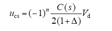
其中,n = 1表示传感器1出现故障;n = 2表示传感器2出现故障。
传感器的故障包含直流干扰和交流干扰两种可能性,因此Vd中可能同时包含有交、直流信号,即
$V_{d} = V_{d0}+V_{da}$
其中,Vd0表示直流分量;Vda表示交流分量。
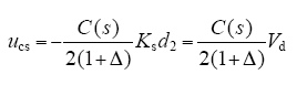
由式(11)可知,ucs和Vd之间的关系是频率的函数,因此可将ucs进一步表示为

其中, 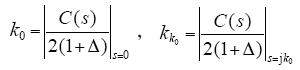
由式(12)可知,如果传感器1发生故障,则ucs和Vd0、Vda的比例系数是负值;如果传感器2发生故障,则ucs和Vd0、Vda比例系数是正值。因此通过分析ucs和Vd0、Vda的比例系数可以识别发生故障的传感器。
$s=kr+n(t)$
图2
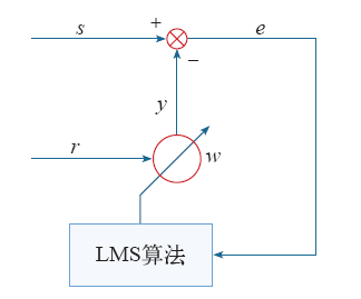
该滤波器通过最小均方算法(Least Mean Square,LMS)调整参考信号的加权因子w来调整补偿信号,使得误差信号的方差最小,随着算法的执行,加权因子w逐渐收敛于k,此时补偿信号y就是原始信号s中和参考信号r相关的成分。如果用Vd0和Vda作为参考信号对uc进行相关滤波,即可分析出ucs、Vd0、Vda的比例系数。原理框图如图3所示。
图3
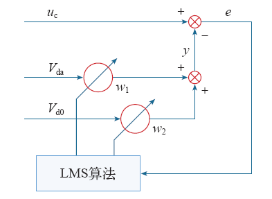
相关滤波算法为
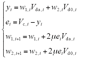
式中,μ为算法的收敛因子;w1,i、w2,i分别为当前时刻Vda和Vd0的权值;w1,i+1、w2,i+1分别为下一时刻Vda和Vd0的权值;yi为当前时刻的补偿信号;ei为当前时刻原始信号和补偿信号的误差。
滤波器稳定之后,有
$w_{1} = k_{0}, w_{2} = k_{k_{0}}$
由式(12)可知,如果w1和w2为负,则说明传感器1有故障;如果w1和w2为正,则说明传感器2有故障。
5 仿真分析
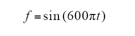
本文以单自由度主动磁悬浮轴承为研究对象,采用Matlab对上文提出的传感器故障识别算法进行仿真。其中对转子施加了一个正弦干扰力来模拟转子在转动过程中的离心力,对传感器施加一个带偏置的正弦干扰信号来模拟传感器探头的故障。对转子施加的干扰力为
对传感器施加的干扰信号为
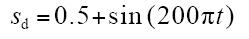
图4
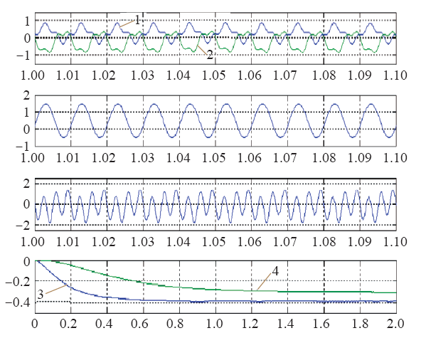
图4
传感器1 发生故障时各处信号波形及识别结果
Fig.4
Signal waveforms and recognition result when the sensor 1 fails
图4中,1为传感器1的输出信号;2为传感器2的输出信号;3为直流相关系数;4为交流相关系数。可以看出,当传感器1发生故障时,识别出来的两个系数均为负值;当传感器2发生故障时,识别出来的两个系数均为正值,与理论分析一致。
6 实验验证
数字滤波器与模拟滤波器相比,具有信噪比高、过渡带性能好、高可靠性及可扩展性、设计灵活方便的优势。因而自适应滤波器的硬件实现一直是自适应信号处理领域研究的热点。随着专用数字信号处理芯片的发展,数字滤波器的可实现性能以及处理速度得到了极大的提升,现场可编程序门阵列(Field-Programmable Gate Array,FPGA)作为一种新型数字信号处理芯片,具有数字信号处理速度快、数据并行处理以及利用硬件编程语言直接进行硬件设计等特点,并且可以使系统的开发周期缩短,成本降低,容易升级和变更。
图5
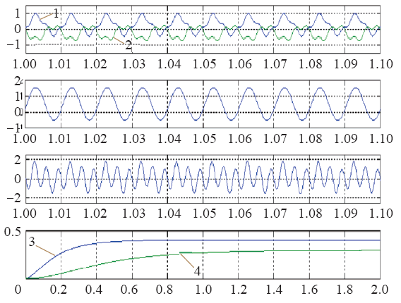
图5
传感器2 发生故障时各处信号波形及识别结果
Fig.5
Signal waveforms and recognition result when the sensor 2 fails
图6
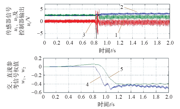
图6
探头1 发生故障对传感器及控制器的影响和故障识别结果
Fig.6
The impact on the sensor and the controller when the sensor 1 fails and the result of fault identification
图7
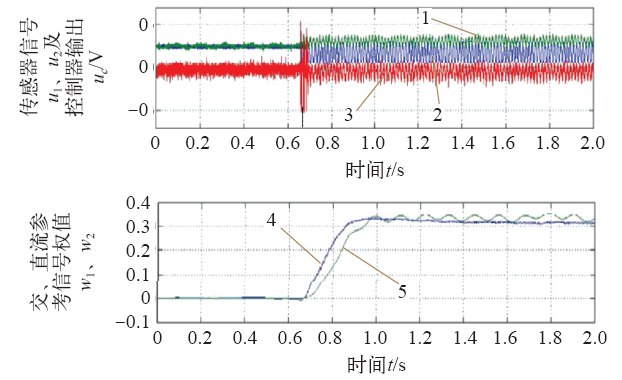
图7
探头2 发生故障对传感器及控制器的影响和故障识别结果
Fig.7
The impact on the sensor and the controller when the sensor 2 fails and the result of fault identification
图7试验中,在ts2时刻将干扰信号施加于传感器2的处理电路,模拟探头2出现故障。可以看出:在ts2时刻之前转子稳定悬浮,在ts2时刻之后转子开始小幅振动,但转子仍然处于悬浮状态。此时传感器1和传感器2信号均出现不同程度的振动,但仍在正常范围之内。与此同时,算法计算结果开始逐渐变化并于故障发生后约 0.35s 稳定于一正值。实验结果与理论分析一致。
7 结束语
本文针对采用差动式位移传感器的主动磁悬浮轴承系统研究了传感器故障的检测方法,分析了不同类型的传感器故障的特点及识别方法,针对传感器的功能受损性故障提出了一种基于LMS自适应滤波的故障传感器识别算法。首先从理论上证明了该算法的可行性,然后采用Matlab对该算法进行了仿真研究,并结合基于FPGA所设计的自适应滤波器对故障信号进行实验验证。研究结果表明该方法可以有效地识别出故障传感器。本文的研究结果为提高主动磁悬浮轴承位移检测系统的可靠性提供了一种新的实现方法。
参考文献
传感器冗余的磁悬浮轴承转子系统研究
[J].
Active magnetic bearing system with redundant sensors was constructed. Five degree of freedom simulation model based on ADAMS and MATLAB was established, and influence of sensor location on dynamic characteristics of the system was analyzed. Incomplete differential PID and fuzzy-PID control programs based on TMS32028335 DSP were compiled. Diagnostic method of sensor fault was designed. Proof tests were implemented by means of cutting sensor cable artificially. Results show that the system can run safely after one of the sensors is damaged.
Active magnetic bearing rotor system with redundant sensors
[J].
Active magnetic bearing system with redundant sensors was constructed. Five degree of freedom simulation model based on ADAMS and MATLAB was established, and influence of sensor location on dynamic characteristics of the system was analyzed. Incomplete differential PID and fuzzy-PID control programs based on TMS32028335 DSP were compiled. Diagnostic method of sensor fault was designed. Proof tests were implemented by means of cutting sensor cable artificially. Results show that the system can run safely after one of the sensors is damaged.
自适应陷波器的原理、应用及其算法仿真
[J].
The theory, application and algorithm simulation of adaptive notch filter
[J].
自适应滤波的原理和应用
[J].
Principle and application of adaptive filtering
[J].
标准串行LMS自适应滤波器的FPGA实现
[J].
FPGA implementation of standard serial LMS adaptive filter
[J].
LMS自适应滤波器模块化设计及其FPGA实现
[J].
Modular design of LMS adaptive filter and its FPGA implementation
[J].
主动磁悬浮轴承位移传感器故障识别
[J].
Fault diagnosis of displacement sensors of active magnetic bearing
[J].
High temperature displacement sensor
[J].
DOI:10.3390/s19163489
URL
PMID:31404970

To perform geodetic measurements of displacements of the ground and manmade constructions, stabilised reference points are needed from which control points on the object or its surroundings could be measured. Reference points are most commonly stabilised with reinforced concrete pillars; however, they are not always constructed in an appropriate manner. The influence of temperature variation within a pillar on the position of the fixed screw for forced centring is not negligible and should be considered when performing precise measurements. In this research paper, the displacement of a pillar was calculated as a result of the temperature changes in the pillar, and then an experiment was performed in which the pillar was heated from one side, and the horizontal displacement of the fixed screw for forced centring was measured. Both, calculations and measurements, show that at a temperature difference of 16.2 °C, the fixed screw on a 1.5 m high pillar moves by approximately 1 mm, which is a displacement that should be taken into account in precise measurements.
Thick film radial position sensor for high temperature active magnetic bearing
[C].
Deagnostic of rotating machinery with magnetic bearing & rigid rotor
[C].
Self-sensing in fault tolerant magnetic bearings
[J].DOI:10.1115/1.1383257 URL
Fault tolerant homopolar magnetic bearings
[J].DOI:10.1109/TMAG.2004.833428 URL
Fault tolerant magnetic bearings
[J].DOI:10.1115/1.2818501 URL
Fault tolerant control of active magnetic bearings
[J].
基于LMS算法和Matlab的自适应滤波器的设计
[J].
Design of adaptive filter based on lms algorithm in Matlab
[J].
