


1 Introduction
Squirrel-cage induction motors are widely used in various industries, its mechanical failure is dominated by broken bars and eccentricity[1]. In the ideal case, the axis of the induction motor stator and rotor should be ta the same point. But due to manufacturing tolerance or operating wear, it will produce a circle eccentricity between the stator and the rotor. This phenomenon is particularly serious in large submersible motors. As a typical type of induction motor, large submersible motors have their unique working condition, which determine their features. In order to be put into deep wells, motors have restricted diameter while elongated length to gain enough power. Illustrated by the case of YBQ1200-4, the prototype in this paper, its stator has a length of 1400mm while less than 350mm in diameter. Such a slender shape easily leads to rotor bending under gravity, namely nonuniform air gap. Meanwhile, the cost will be huge if the motor breaks down due to the rub of the stator and rotor. Based on the above mentioned, noninvasive detection of air gap eccentricity is an urgent task to guarantee the operational reliability of submersible motor.
There are two basic forms of eccentricity. One case when rotor rotates around its geometric axis which is not coincident with geometric axis of the stator is called the static eccentricity, which is characterized by the spatial position of minimum length of the gap with respect to the stationery stator while air gap at different positions stay constant when rotating. Another case when rotor rotates around geometric axis of the stator while geometric axes of the stator and rotor misalign is called the dynamic eccentricity. The feature of dynamic eccentricity is that spatial position of minimum length of the gap varies with the rotation of the rotor. Some other complex eccentricity is basically combinations of static and dynamic eccentricity. A further study in this field is proposed by Akiyama[2], who proposed axial oblique eccentricity. In this case, the degree of eccentricity varies with inclination angle of rotor and axial direction. Later, Tenhumen[3] and Kelk[4]did research on such eccentricity. After that, curved eccentricity model is proposed by Qiang Lv[5] for the first time.
When the rotating electric machine produces the air gap eccentric fault, it also causes another problem-vibration. In this aspect, the research needs to be considered from the aspects of electromagnetism, mechanics and mechanics, and it is more complicated. However due to the fact that rotor eccentricity fault caused by unbalanced magnetic pull will also have an important influence on the vibration motor: motor, the magnetic force will also occur in the stator and rotor, and eccentric fault generated magnetic field distribution will also change, resulting in the magnetic force imbalance. A lot of factors can lead to the emergence of unbalanced magnetic force. The motor stator and rotor is not concentric, which is one of the common factors. In addition, it is not only due to the air gap eccentricity, but also due to other factors, such as the material magnetizing uneven or the excitation winding failure. Other reasons also lead to unbalanced magnetic pull. The root cause of the unbalanced magnetic pull is the asymmetry of the circuit or the magnetic circuit in the motor. The significance of the study of unbalanced magnetic pull is that it will help to improve the mechanical design and the specification of the bearing. The effect of unbalanced magnetic pull on the eccentric fault may be insignificant, but with the increasing degree of eccentricity, the role of unbalanced magnetic pull will become even greater, which cannot be ignored. Serious when can cause bearing wear, need to spend a lot of manpower and material resources to maintain, overhaul and shorten the service life. The unbalanced magnetic pull of cage induction motor has been studied in the literature. Rotor eccentricity fault caused by the minimum air gap magnetic density increases, resulting in the role of the radial force on the rotor, unbalanced magnetic pull effect will make the rotor far away from the center, resulting in increased eccentricity fault.
Unbalanced magnetic pull is an important problem in all motors, and the discussion about unbalanced magnetic pull in other motors is recorded in Ref.[6-11]. However, due to the complexity of the rotor of induction motor, the current needs to be calculated, compared to the synchronous motor, the difficulty of the unbalanced magnetic force calculation of induction motor is greatly increased. The research of Ref.[12] shows that the parallel structure of the cage type of the rotor will weaken the unbalanced magnetic pull. In addition, the parallel branches of the stator will also have some weakening effect on the unbalanced magnetic pull[13]. The effect of slot effect on the unbalanced magnetic pull is studied in the Ref.[14]. The calculation of unbalanced magnetic force as a single radial centrifugal force was once the most early research method, and the Bradford[15] and Binns[16] in the early studies were also quantitatively analyzed. The accurate measurement of unbalanced magnetic pull is one of the necessary steps. The quantitative calculation of unbalanced magnetic pull is always a complicated task, and there are few literatures about it. So far, there has not been a precise and universal nonlinear analytical expression for the calculation of unbalanced magnetic pull. Therefore, there will be a large number of studies in this area in the future to fill the gap. There are two main modeling methods in the study of unbalanced magnetic pull: analytic method and finite element method.
The unbalanced magnetic pull is an important question in all the other motor, motor of unbalanced magnetic pull discussed in the Ref.[18] records. However, because of the complexity of rotor induction motor, the current needs to be calculated and compared to the synchronous motor, the calculation of unbalanced magnetic pull induction motor is greatly increased. Research literature indicates that rotor cage bar parallel structure can weaken the unbalanced magnetic pull. In addition to the stator parallel branches will produce some unbalanced magnetic pull weakened. The effect of slot effect on the unbalanced magnetic pull is studied in the literature. The calculation of unbalanced magnetic force as a single radial centrifugal force was once the most early research method, and the Bradford and Binns in the early studies were also quantitatively analyzed. The accurate measurement of unbalanced magnetic pull is one of the necessary steps. The quantitative calculation of unbalanced magnetic pull is always a complicated task, and there are few literatures about it. So far, the calculation of unbalanced magnetic force field has not been a precise and widely used nonlinear analytical expressions of good. Therefore, will still have a lot of research in this area appears to fill the blank after. Study on the unbalanced magnetic pull, there are mainly two kinds of modeling methods: analytic method and finite element method.
The initial modeling is often applied to the magnetic circuit of the linear, literature established the first consider the nonlinear saturation of magnetic circuit model and the graphic method was used in the gas gap magnetic flux is decomposed into two flux wave, are given in the Ref.[19] the theory of mathematical proof. The relative rotation speed of the magnetic flux wave will determine whether the radial unbalance magnetic pull is stable in one direction or in the rotation. The static eccentricity tends to produce a tension that is stable in one direction, while the unbalanced magnetic pull vector generated by the dynamic eccentricity is synchronous with the rotor.
2 Establishment of Curved Eccentric Mode
In fact, the eccentricity of the motor air gap is relatively complex, which is rather difficult to describe with an accurate mathematical expression. Not only because the static and dynamic eccentricity tend to coexist, but also these eccentricities are not uniform in axial direction due to the deflection of the shaft. And even mixed eccentricity is idealized to some extent.
A curved eccentricity model of large motor is established. By using analytical method and finite element method, horizontal motor shaft deflection is calculated and a general mathematical description of curved eccentricity is summarized.
2.1 Shaft rotation characteristics
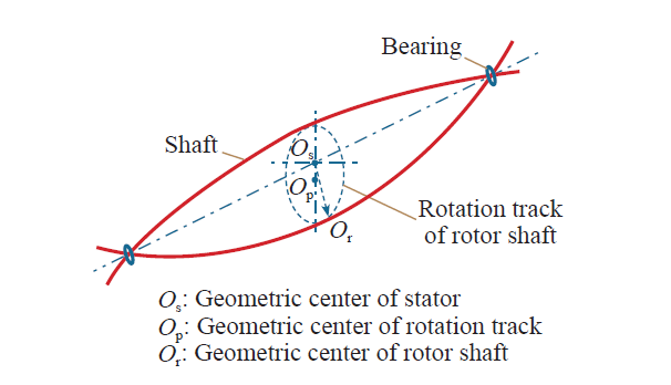
The rotating condition of large motor shaft is quite complex, especially in horizontal or inclined installed ones. The rotor is almost inevitable presence of static and dynamic eccentricity simultaneously. Since the rotor is loaded under gravity and unbalanced magnetic pull force, the shaft will bend, making the axial distribution of eccentricity inconsistent. In addition, bearing fault, installation error and other factors also make eccentricity fault more complicated. Figure 6 shows the horizontal motor shaft to rotate the model. To simplify the theoretical analysis, this model is proposed to rationalize the following assumptions:
1) Bearings are rigid at both ends, while its stiffness is consistent horizontally and vertically.
2) The errors in manufacture and installation are negligible, therefore the z-axis is the geometric axis of the stator core.
3) Gravity, unbalanced magnetic pull and bending stresses are considered to produce deflection factors, other forces negligible.
Based on rotor dynamics theory, when both ends of the horizontal shaft bearings are rigid, geometric center of shaft rotation track op is a perfect circle, while its center is located in the negative y-axis axle.
As for the vertical motor, the influence of gravity on the deflection is negligible; therefore, geometric center of shaft rotation track coincides with geometric center of the stator.
Fig.1
2.2 Calculation of bending stiffness
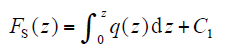
Shaft bending stiffness can be obtained by analytical method. Differential equations of flex shaft shear and differential relations between shearing force, bending moment and load density can be expressed as
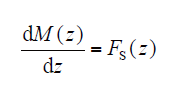
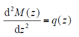
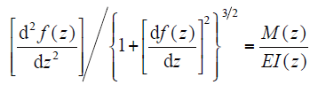
where Fs(z) is the shearing force; M(z) is the bending moment; q(z) is the load density; f(z) is the deflection at corresponding position of the shaft; E is the elastic modulus; I(z) is the inertia moment at corresponding position of the shaft. Formula (35) and (36) shows that the shear and bending moment can be expressed as
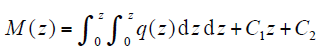
where C1 and C2 are constants of integration, and can be obtained by known displacement or displacement constraints. In engineering practice, the angle of rotation of the shaft is generally small, and therefore, the value of [df(z)/dz]2 is much less than 1, so the formula (37) can be simplified as
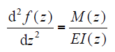
Integrating formula (39) twice can get expression of the deflection of the shaft
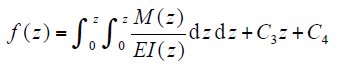
In which C3 and C4 are constants of integration that can be determined by the boundary conditions of the displacement. Finally, the bending stiffness at the center of the shaft can be obtained
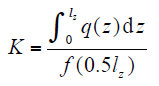
where lz is shaft length.
3 Modeling of curved eccentricity and analysis
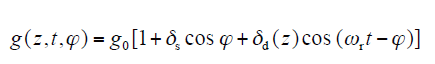
Based on the detection of air gap eccentricity, only the form of gap eccentric is required, rather than the knowledge of their specific values. Assuming shaft and rotor are mounted concentrically without mass eccentricity while no static rotor eccentricity exists, curved eccentricity is defined as follows: the curved eccentricity is a special form of dynamic eccentricity when the rotor is axially arched due to shaft bending. Therefore the basic equation of radial air gap length can be expressed as
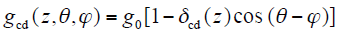
where z is the axial position; θ is the rotor angular position; φ is the stator angular position; g0 is the radial length of the air gap in healthy motor; δcd(z) is the eccentricity. The eccentricity δcd(z) is defined as
where f(z) is the rotor deflection that varies along the axial position z in a certain law.
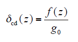
As the distinctiveness of curved eccentricity, the eccentricity degree δcd(z) is the critical parameter different from the other forms of eccentricity. To determine the function of the eccentricity degree, take the wet submersible motor YBQ1200-4 for example by using finite element method.
When the motor is running, the bending the shaft is caused by a variety of forces. -To simulate the deflection results in curved eccentric motor, an equivalent force perpendicular to rotary shaft is applied to the core segments while two ends of the guide bearing are constrained without displacement so the shaft is bent. In this way, the deflection at various points in the shaft core segments can be analyzed in order to calculate the function of the eccentricity degree.
Fig.2
After observing the simulation values of the deflection, it can be found that quadratic function can be used to fit accurately. Thus, the function of the eccentricity degree can be expressed in the following form
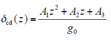
where A1, A2, A3 are fitting parameters. Under such circumstance, A1 = -0.00000205, A2 = 0.00303, A3 = 0.25873.
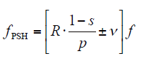
Cameron et al.[14] proposed that stator current contains some component of a specific frequency when eccentricity exists. Frequency component related to the eccentricity can be expressed as
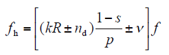
where nd is the order of eccentricity (nd = 0 for static eccentricity and nd = 1, 2, 3… for dynamic eccentricity); While f is the fundamental supply frequency; R is the number of pole pairs; k is any integer; v = ±1, ±3, ±5, etc. is the order of the stator time harmonics that are present in the power supply driving the motor[15].
Fig.3 to 5 show the frequency spectrum of an induction motor with a dynamic eccentricity condition, that of one with curved eccentricity condition, and that of a healthy one.
Fig.3
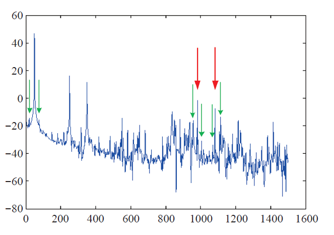
Fig.4
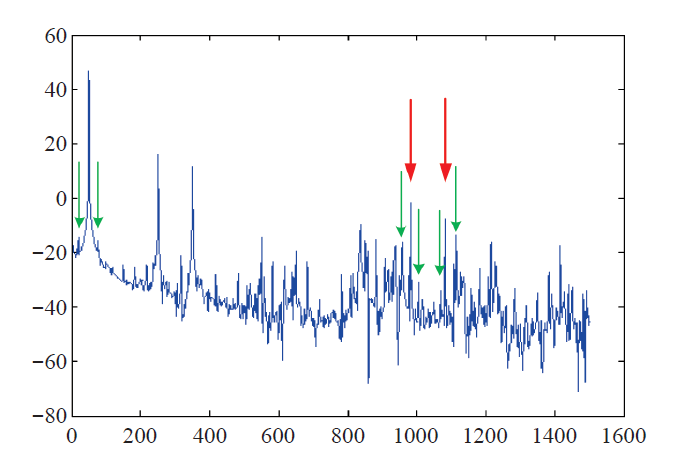
Fig.5
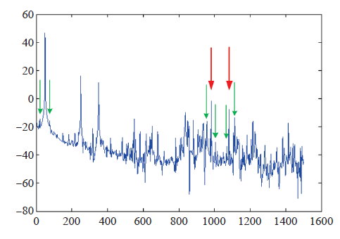
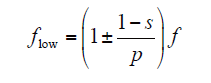
In addition to the fundamental harmonic, other harmonics caused by rotor slotting are present in a healthy motor and can be clearly seen in Fig.5. The frequency of these harmonics is as follows
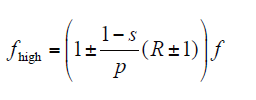
In comparison to Equ.(13) and (14), it can be seen that the principal slot harmonics (marked in the figures with red arrow) are also given by Equ.(13) with k = 1 and nd = 0.
Considering (14) and determining the slip (about 0.017), the slotting harmonics of the motor have frequencies 1 082 and 982 Hz, as shown in Fig.3. Fig.4 also show that in the dynamic eccentricity, extra harmonics emerge around the fundamental and slotting harmonics. The frequency of these harmonics can be calculated as follows
Thus, the following frequencies of the harmonics can be predicted: 74.575, 25.425, 1 059.625, 1 008.875, 959.625, and 1 108.875. These harmonics are illustrated in figures with green arrow. In different eccentricity conditions these harmonics may be amplified or weakened depending on the design conditions and performance of the motor. However, the presence of even one of these harmonics is a good reason for suspecting possible eccentricity in the motor.
4 Vibration Analysis in Curved Eccentric Motor
4.1 Calculation of UMP
If the motor is in the condition of complex mixed eccentric fault (i.e. there are static and dynamic eccentricity, and cannot determine whether the dynamic eccentricity is axial uniform), the air gap length can be expressed as
where g0 is the air-gap length of healthy motor; δs is static eccentricity degree; δd(z) is axial eccentricity degree function of dynamic eccentricity, since the dynamic eccentricity may be axially inhomogeneous, so it is a function of the axial position of the z. The inverse equation of air gap length can be written as
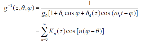
In the last section, the air gap permeance distribution function adopted simplified calculation is more accurate. Is still using Fourier series analysis, air gap permeance and air gap length is inversely proportional.
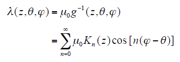
where Λn(z) = μ0Kn(z), Λn(z) is the amplitude of the second n item in the Fourier series expansion. Stator current density is
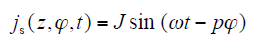
And the air gap flux density can be expressed as
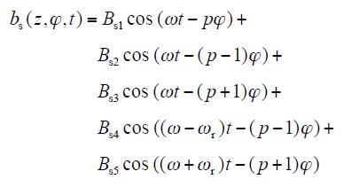
where Bs1 = μ0J/gp; Bs2 =Bs3 =μ0Jδs/gp; Bs4 = Bs5 = μ0Jδd(z)/gp.
By the air gap magnetic density, the radial force of the air gap can be obtained.
Obviously
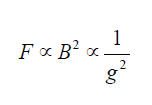
While
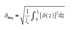
where δdeq is dynamic equivalent eccentricity degree, It is said that when the unbalanced magnetic pull of the same size is generated, the curved eccentricity expressed by δ(z) (or the other type of axial eccentric) is the same as the effect of dynamic eccentricity of δdeq.
By bringing in δdeq, the variable z can be eliminated, Let Bs4 = Bs5 = μ0Jδdeq/gp, the Equ.(21) can be expressed as

4.2 Finite element simulation of unbalanced magnetic pull
In order to further identify whether the uniform axial dynamic eccentricity fault, unbalanced magnetic pull by axial three-dimensional finite element of different eccentricity uniform dynamic eccentricity and dynamic eccentricity fault arc under simulated. The model of different degree of eccentricity (from 0 to 0.5) of the axial uniform dynamic eccentricity under the unbalanced magnetic pull of simulation, as shown by the red curve in Fig.4, with the increase of eccentricity, unbalanced magnetic pull growth close to the growth trend of the quadratic function. Accordingly, the motor vibration signal spectrum related to the amount of amplitude detection can be quantitative detection of dynamic eccentricity and eccentricity. Also even when the eccentricity is very small, there will still be some unbalanced magnetic pull, which is also the motor in after the factory in the operation of the will from the minimum of the initial eccentricity develops gradually to cause serious eccentricity fault, when the eccentricity is equal to 0.15, unbalanced magnetic pull the size of has reached 500N, is cannot be ignored. At the same time, the arc deflection model also the simulations are carried out. Such as in Fig.6 blue marker, curved dynamic equivalent eccentricity Delta deq = 0.468, calculate unbalanced magnetic pull 3 168N, for dynamic eccentric eccentricity -UMP curve trend also with better visible arc eccentric equivalent dynamic eccentricity is appropriate.
Fig.6
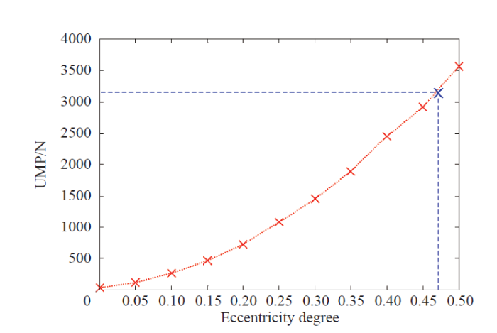
Note that the average arc eccentric eccentricity and eccentricity is equivalent parameters on arc faults of different points of the eccentric. The eccentricity of the same model, numerical two parameters are different, usually the equivalent eccentricity of eccentric arc than the average small eccentricity. The 3.10 type eccentric fault arc fitting function is represented as an example, the average eccentricity is 0.437, the equivalent eccentricity is 0.468. In Figure 4.4, the unbalanced magnetic pull between 0.437 and 0.468 corresponding to the eccentricity of nearly 1 000N.
It can be seen that both the current spectrum analysis and the vibration frequency spectrum analysis are unable to distinguish the dynamic eccentricity and the axial uniform dynamic eccentricity. Therefore, the identification of dynamic eccentricity fault is an axial uniform or dynamic arc eccentric fault, it is necessary to the vibration spectrum and the current spectrum of the comprehensive analysis.
5 Conclusion
Based on the above analysis, regardless of the current signal detection and vibration signal detection can separate detection of the eccentric fault type (static, dynamic or mixed), can quantitatively detect eccentricity. But for dynamic arc eccentricity, both the current signal and the vibration signal characteristic of the dynamic eccentricity are no different from the dynamic eccentricity. At the same time, we also pay attention to, dynamic arc eccentric in the current signal and vibration signal quantification of dynamic eccentricity is not the same (i.e. section mentioned average eccentricity and eccentricity of equivalent differences), resulting in a dynamic curved eccentricity become a special dynamic eccentricity.
It is also due to the fixed dynamic arc eccentric in current signal and vibration signal will reflect the different quantitative, through a comparative analysis of the amplitude of the vibration detection signal spectrum characteristics of amplitude and current signal characteristic quantity, whether the differential dynamic eccentricity eccentric arc. Both the current and the vibration signal detection methods can determine the static and dynamic types of eccentricity. If the dynamic eccentricity is contained, the amplitude of the characteristic value of the spectrum of the vibration signal can be compared with the amplitude of the characteristic value of the current signal. If the dynamic eccentricity ratio is not the same as the characteristic quantity which is detected by the current signal and the vibration signal, it indicates that the curved eccentricity exists.
参考文献
Improved online condition monitoring using static eccentricity-induced negative sequence current information in induction machines
[C].
Unbalanced-heating phenomenon of induction motor with eccentric rotor
[C].
Electromagnetic forces in cage induction motors with rotor eccentricity
[C].
Modeling and analysis of cage induction motors under rotor misalignment and air gap eccentricity
[C].
Inductances evaluation of a squirrel-cage induction motor with curved dynamic eccentricity
[J].DOI:10.5370/JEET.2014.9.5.1623 URL [本文引用: 1]
Saturation effects on unbalanced magnetic pull in a hydroelectric generator with an eccentric rotor
[J].
Finite-element analysis of unbalanced magnetic pull in a large hydro-generator under practical operations
[J].DOI:10.1109/TMAG.2007.916023 URL
Unbalanced magnetic pull in train-lighting brushless alternators with static eccentricity
[J].DOI:10.1109/TVT.2007.901966 URL
Unbalanced magnetic forces in permanent-magnet brushless machines with diametrically asymmetric phase windings
[J].
Nay L H A. Effect of radial magnetic forces in permanent magnet motors with rotor eccentricity
[J].DOI:10.1109/TMAG.2007.896204 URL
Unbalanced force calculation in switched-reluctance machines
[J].DOI:10.1109/20.822543 URL
Sources and characteristics of unbalanced magnetic pull in three-phase cage induction motors with axial-varying rotor eccentricity
[J].DOI:10.1109/TIA.2010.2090845 URL
The calculation and measurement of unbalanced magnetic pull in cage induction motors with eccentric rotors. Part 2: Experimental investigation
[J].
Effects of the slot harmonics on the unbalanced magnetic pull in an induction motor with an eccentric rotor
[J].DOI:10.1109/TMAG.2007.899470 URL [本文引用: 1]
Unbalanced magnetic pull in a 6-pole induction motor
[J].DOI:10.1049/piee.1968.0282 URL [本文引用: 2]
Identification of principal factors causing unbalanced magnetic pull in cage induction motors
[J].DOI:10.1049/piee.1973.0072 URL [本文引用: 1]
A multisliced finite-element model for induction machines incorporating interbar current
[J].DOI:10.1109/TIA.2008.2009484 URL
Saturation effects on unbalanced magnetic pull in a hydroelectric generator with an eccentric rotor
[J].
The calculation and measurement of unbalanced magnetic pull in cage induction motors with eccentric rotors. Part 1: Analytical model
[J].
