

1 引言
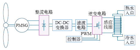
本文以新能源发电技术为基础,采取电磁感应加热的方式将风光互补电源电能转化为热能,利用水为媒介将热能存储起来,系统整体结构如图1所示。同时针对24kHz/100kW的电磁热储能系统,对电磁热储能系统的整体工作性能进行了多方面的研究分析,包括:电磁感应加热模型的电磁涡流场分析,流体温度场特性研究,感应加热电源的串联谐振电路的谐振状态仿真分析。最后通过实验验证了电磁热储能系统理论分析的正确性,为电磁热储能系统感应加热技术的研究与开发提供了一定理论依据。
图1
2 电磁热储能系统感应加热结构与工作机理
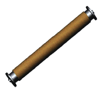
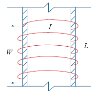
电磁热储能系统以感应加热的方式将电能转化为热能并储存起来。其中电磁加热部分的加热单元结构主要包括电磁加热线圈、金属圆柱加热单元。图2为加热结构的物理模型,其中金属加热单元附有进水口、出水口,可供流水通过。其表面缠有电磁加热线圈对通过的流水进行感应加热。
图2
当铁心线圈通以交流电流时线圈周围会产生交变磁场,在铁心中便有感应电动势生成感应电流——涡流。涡流的值取决于磁场的强弱,磁场强度在紧靠线圈的地方最强,随其距离的平方而减小。由于趋肤效应的影响,电流只在导体表面层通过,表面层的深度与导体的性质和电流频率的高低有关,通常将此表面层的深度或厚度称为穿透深度。
设穿透深度为∆,则∆由下式确定
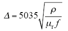
式中,f为交变电流频率;μr为相对磁导率;ρ为导体的电阻率。
以图3所示金属圆柱剖面图为例,对加热单元进行热功率推导计算。
图3
对于金属圆柱体感应加热,感应线圈所消耗的电功率为
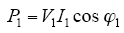
式中,I1为线圈电流;cos φ1为感应线圈中的功率因数。由此电磁感应原理钢管壁中产生感应电动势为
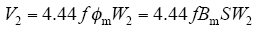
式中,f为电源频率;Bm为金属管壁中磁感应强度;S为钢管壁截面积;W2为钢管的等效匝数。
S = πDa,D为钢管的平均直径,a为管壁的厚度。则

在V2作用下钢管壁中产生感应涡流I2沿管壁流通产生热量。且
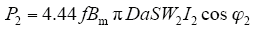
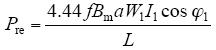
加热单元所需的热功率应与感应线圈所消耗的电功率相平衡,设加热单元表面积为S0,且S0 = πDL,L为线圈高度,其中功率因数cos φ1取0.945,由此可得加热单元单位表面积发热功率为
3 电磁热储能系统感应加热电磁场及温度场分析
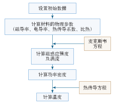
在温度场分析之前,首先需要对模型电磁场进行仿真计算,并将磁场求解得到的涡流功率作为温度场求解的内部热源,再根据热传导方程及在一定边界条件下进行计算求解,从而确定温度分布情况。具体的计算流程图如图4所示。
图4
首先,在三维涡流场中电磁场麦克斯韦方程组满足的方程式为
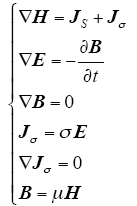
式中,B为磁感应强度矢量;H为磁场强度矢量;E为电场强度矢量;JS为传导电流密度;Jσ为涡电流密度;σ为电导率;μ为磁导率。
对电磁热储能系统流体温度场进行有限元分析,建立的连续性方程、动量守恒方程和能量守恒方程为
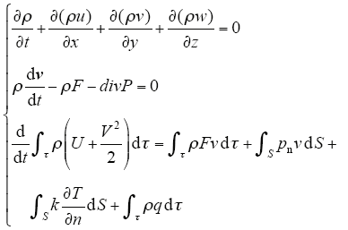
式中,ρ为流体密度; 


利用Ansoft-Maxwell软件,对加热单元进行电磁涡流场建模仿真,金属管材料选取为Q235。涡流场仿真相关参数如表1所示。
表1 电磁涡流场仿真相关设置参数
Tab.1
| 参 数 | 数 值 |
|---|---|
| Q235电阻率/Ω·m | 14×10-8 |
| Q235相对磁导率 | 250 |
| Q235导热系数/[W/(m·k)] | 43 |
| 线圈电流有效值I1/A | 200 |
| 线圈截面积/mm2 | 50 |
| 线圈匝数N | 100 |
| 功率因数cos φ1 | 0.945 |
| 电源频率f /Hz | 24 000 |
| 金属管长度/mm | 1 000 |
| 金属管外径/mm | 108 |
| 金属管壁厚a/mm | 2 |
| 涡流透入深度Δ/mm | 0.078 |
对平行放置的加热单元进行磁场仿真,考虑邻近效应,调整合适的安置间距,分别设置加热单元的平行间距为20cm、25cm、30cm、40cm、50cm,对比加热单元表面的磁场分布可知,加热单元平行间距在约30cm时,感应加热单元表面的磁场分布相对较优,有效电磁感应强度更有利于工程应用,其中Bm趋近0.05T。仿真结果如图5所示。
图5
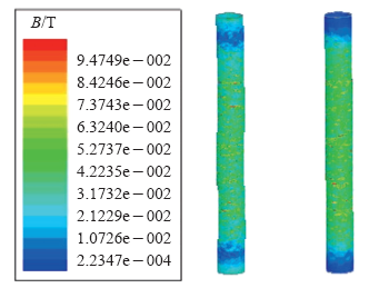
图5
24kHz/30cm间距金属管表面磁感应强度云图
Fig.5
24 kHz/30cm distance metal tube surface magnetic induction intensity
对感应加热单元升温过程进行系统仿真。三维流体温度场仿真相关参数如表2所示。
表2 流体温度场仿真相关参数
Tab.2
| 参 数 | 数 值 |
|---|---|
| 参考压力/Pa | 101 325 |
| 参考重力/(N/s2) | 9.81 |
| 入水口速度v/(m/s) | 0.05 |
| 外表面散热系数/( W/m2) | 5 |
| 体热功率密度P/( W/m3) | 1.39×10⁸ |
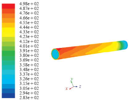
由上可得三维流体温度场的仿真结果如图6所示,从中可以看出感应加热单元中水的升温过程,同时当进水口流量为424mL/s时,出水口温度将趋近60℃。
图6
4 感应加热电源串联谐振电路仿真
电磁绕组电感L、谐振电容C以及负载等效电阻Req构成的串联谐振等效电路如图7所示。
图7
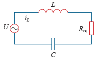
串联谐振负载的阻抗Z和电流I分别为
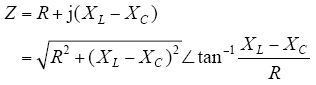

式中,XL = ωL, 
频率。
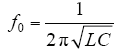
若XL = XC,则φ = 0,这时电路处于谐振状态,谐振频率为
电路中的电压和电流同相位,电路阻抗为纯电阻Req,且等效电阻为最小值,负载电流达到最大。在发生串联谐振时,电感L和电容C两端的电压等于外加电压UDC的值的Q倍,Q为谐振电路品质因数,且
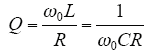
式中,ω0为谐振时的角频率。如果谐振电路的品质因数Q足够高并且工作频率接近负载的固有谐振频率,输出电流近似为正弦波,其输出功率Po可表示为
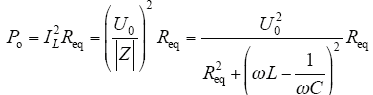
式中,IL为负载基波电流的有效值;U0为负载基波电压的有效值;ω为逆变器的工作频率。
对于串联型谐振逆变器来说,当L、C发生串联谐振时,负载等效阻抗呈现低阻抗。由于逆变器输入端直流母线连接有直流滤波电容,相当于恒压源。因此,在工作时,逆变器输出电压近似为矩形波,输出电流则近似为正弦波。
以24kHz/100kW的感应加热电源为研究对象,以全控型功率器件IGBT和串联谐振负载为核心,同时加入锁相环功能,并且利用Matlab软件建立仿真模型。感应加热电源的基本结构由三相电源、整流电路、滤波电路、逆变电路、控制电路、负载等组成。系统的结构图如图8所示。其中:
图8
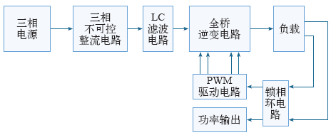
(1)整流电路的作用是将交流电转换为直流电,采用不可控整流可使电路简单,便于控制,减小功率损耗。
(2)滤波电路的作用是减小电路的谐波干扰,提高逆变器的功率因数,减小脉动,使逆变电路输入较平稳的直流电压。
(3)逆变电路的作用是将滤波电路输出的直流电转变成交流电,提供给负载。系统采用IGBT构成全桥逆变电路,使用PWM信号驱动。
(4)锁相环电路的作用是进行频率跟踪,对负载电路的电压信号进行采集,经过鉴相器,低通滤波器和压控振荡器处理,从而调整逆变电路中驱动信号的相位,实现对负载谐振频率的自动跟踪,使逆变器工作于准谐振状态。
采用Matlab/Simulink建立感应加热电源仿真模型,如图9所示。
图9
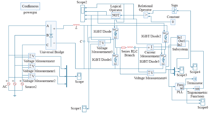
表3 感应加热电源仿真参数
Tab.3
| 参 数 | 数 值 |
|---|---|
| 三相电源电压有效值/V | 220 |
| 三相电源频率/Hz | 50 |
| 直流滤波电感Ld/mH | 5 |
| 直流滤波电容Cd/μF | 5 000 |
| 串联谐振电路等效电阻R/Ω | 2.4 |
| 谐振电感L/mH | 0.014 7 |
| 谐振电容C/μF | 17 |
| 锁相环初始频率/Hz | 24 000 |
| 锁相环参数Kp | 0.6 |
| 锁相环参数Ki | 10 |
图10
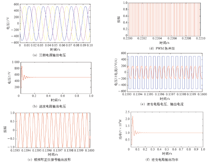
图10
感应加热电源谐振电路仿真波形
Fig.10
Induction heating power supply resonant circuit waveforms
5 结论
本文针对大功率电磁热储能系统,通过分析感应加热结构的原理特点,对其关键技术进行了研究,对系统的电磁场和流体温度场进行了仿真研究及实验对比,并对感应加热电源的串联谐振电路进行了仿真研究。得到了以下结论:
(1)通过对电磁热储能系统加热模型的感应加热原理的研究,以及电磁场和流体温度场的分析,得到了感应加热模型的电磁及温度特性。
(2)对感应加热电源串联谐振电路进行了建模与仿真,得到了谐振状态下的电路特性曲线,为感应加热电源的器件选型提供了依据。为电磁热储能系统的感应加热控制电源的设计提供了一定的理论依据。
参考文献
太阳能辅助加热电蓄热系统的设计应用
[J].
The design and application of solar energy supplementary and electricity heat storage system
[J].
风电供热提高低谷风电消纳能力评估
[J].
Evaluation of wind power heating in facilitating wind power integration capability during valley load period
[J].
电蓄热生活热水供应系统
[J].
The electric thermal storage life hot water supply system
[J].
利用蓄热式电采暖提高电网风电接纳能力的研究
[J].
Research on improvingthe capability of the grid to accept wind power by regenerative electric heating
[J].
交变磁场中圆柱铁磁材料涡流热功率计算
[J].
Cylindrical vortex ferromagnetic materials thermal power calculation in alternating magnetic field
[J].
水暖加热系统感应加热电源Matlab仿真研究
[J].
Research on matlab simulation to induction heating power supply in the plumbing heating system
[J].
Power measurement by output-current integration in series resonant inverters
[J].DOI:10.1109/TIE.2008.2003215 URL [本文引用: 1]
双闭环控制感应加热电源设计与仿真分析
[J].
Design and simulation of double-closed loop control for induction heating power
[J].
Numerical analysis of the worming process trought induction in matters of thermal treatment
[J].
DOI:10.1088/1361-6528/ab662f
URL
PMID:31887729
[本文引用: 1]

Ferromagnetic nanorings exhibit tunable magnetic states with unique magnetization reversal processes and dynamic behavior that can be exploited in data storage and magnonic devices. Traditionally, probing the magnetization dynamics of individual ferromagnetic nanorings and mapping the resonance modes has proved challenging. In this study, micro-focused Brillouin light scattering spectroscopy is used to directly map the spin wave modes and their intensities in nanorings as a function of ring width and applied magnetic field. Micromagnetic simulations provide further insights into the experimental observations and are in good agreement with the experimental results. These results can help in improving the understanding of spin wave confinement in single elements for magnonic devices and waveguides.
Review of molten-salt thermocline tank modeling for solar thermal energy storage
[J].
DOI:10.1080/01457632.2012.746152
URL
[本文引用: 1]
Molten-salt thermocline tanks are a low-cost option for thermal energy storage in concentrating solar power systems. A review of previous experimental and numerical thermocline tank studies is performed to identify key issues associated with tank design and performance. Published models have shown that tank discharge performance improves with both larger tank height and smaller internal filler diameter due to increased thermal stratification and sustained outflow of molten salt with high thermal quality. For well-insulated (adiabatic) tanks, low molten-salt flow rates reduce the axial extent of the heat-exchange region and increase discharge efficiency. Under nonadiabatic conditions, low flow rates become detrimental to stratification due to the development of fluid recirculation zones inside the tank. For such tanks, higher flow rates reduce molten-salt residence time inside the tank and improve discharge efficiency. Despite the economic advantages of a thermocline tank, thermal ratcheting of the tank wall remains a significant design concern. The potential for thermal ratcheting is reduced through the inclusion of an internal thermal insulation layer between the molten salt and tank wall to diminish temperature oscillations along the tank wall. Future research directions are also pointed out, including combined analyses that consider the solar receiver and power generation blocks as well as optimization between performance and economic considerations.
