


1 引言
三电平逆变器具有输出电压谐波含量低、电压变化率小、EMI小等优点,目前在中高压大功率场合具有十分重要的应用[1]。二极管钳位型三电平逆变器是目前工业应用最广泛的一种拓扑结构,T型三电平拓扑是在二极管钳位型三电平逆变器的基础上改进而来的,其电路每一桥臂上减少了两个钳位二极管,降低了导通损耗,减少了逆变器体积,是很有发展前景的一种逆变器拓扑[2]。但三电平中点钳位型逆变器电路结构存在直流侧中点电位会产生波动的固有缺陷,中点电位的波动对系统的危害巨大,因此必须予以解决。中点电位的平衡控制可以从硬件和软件两方面解决,从降低成本的角度考虑,采用软件方式更具有现实意义。目前常用的软件方法有两种:基于零序分量注入的载波PWM方法和基于冗余小矢量调整的SVPWM方法[3]。但这些调制算法需要大量的计算,以及对扇区或矢量的正负进行判定,繁琐的计算不仅耗费时间,还占用大量的存储空间。预测控制技术是一种线性控制方法,其动态响应快、控制精度高、易于数字化实现。文献[4]将预测电流控制方法应用于两电平电压源型逆变器,该方法能够有效地控制负载电流,具有较快的动态响应,省掉了传统的调制器。文献[5]针对预测控制算法对电感参数敏感的问题,提出一种改进型预测电流控制算法,得到了更好的稳定裕度。文献[6]针对三相三线制电压型逆变器,提出了一种模型预测控制方法,与传统的电流内环–电压外环的控制方法进行了比较,验证了所提方法具有良好的控制性能。但以上文献均未对中点电位的平衡控制问题作出说明,文献[7]针对多电平变流器HVDC系统,提出了一种模块化的模型预测控制方法,提出通过开关状态优化方式减小子模块电容电压的波动范围。文献[8,9]将预测控制方法分别应用于中点钳位型三电平逆变器和有源电力滤波器中,实现了中点电位的平衡控制。
本文在上述研究的基础上,结合现有的预测电流控制方法,研究了一种基于模型预测控制的T型三电平逆变器中点电位平衡控制方法,通过建立特定的性能指标函数,选择最优的开关状态作用于逆变器,省去了传统的调制步骤,仅仅使用预测控制器,控制灵活简单,易于数字化实现,可获得很好的跟踪效果,动态响应快,可实现对中点电压的平衡控制。
2 三电平逆变器的数学模型
2.1 T型三电平逆变器的数学模型
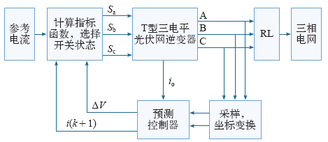
T型三电平光伏并网逆变器的电路拓扑结构如图1所示[10],在此用一个直流电压源代替光伏电池的输出电压,逆变器三相输出通过RL负载与电网并网,三相逆变器由12个开关器件(IGBT)构成,逆变器每一相包含4个开关器件,VTi1和VTi4分别连接直流供给电压的正母线和负母线,VTi2和VTi3连接直流环中点和负载,构成一个双向开关,其中i = a,b,c。C1、C2是分压电容。以a相为例,来说明该电路的工作方式。以分压电容之间的o点为零电位参考点。其中开关管VTa1和VTa3的开关控制信号互补,VTa2和VTa4的开关控制信号互补。当开关管VTa1、VTa2导通,VTa3、VTa4关断时,a相对于零电位参考点o的电平为Udc/2,用P表示;当开关管VTa2、VTa3导通,VTa1、VTa4关断时,a相对于o点的电平为0,用O表示;当开关管VTa3、VTa4导通,VTa1、VTa2关断时,a相对于o点的电平为- Udc/2,用N表示。用S表示开关状态,以上工作方式如表1所示。
图1
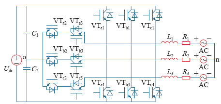
表1 三电平逆变器各相的开关状态
Tab.1
| Sa1 | Sa2 | Sa3 | Sa4 | 输出电平 | |
|---|---|---|---|---|---|
| P | on | on | off | off | +Udc/2 |
| O | off | on | on | off | 0 |
| N | off | off | on | on | -Udc/2 |
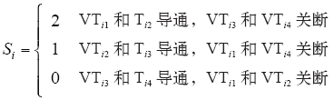
由表1可以看出,定义一个开关函数可以更方便表述。开关函数表示如下
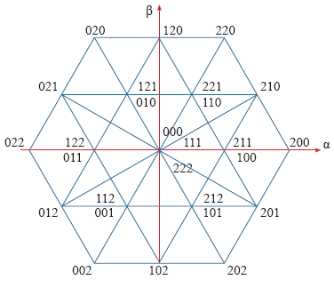
因此三相三电平逆变器就可以输出33 = 27个电平状态组合,对应27组不同的逆变器开关状态,此时可以定义电压空间矢量为[11]
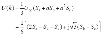
根据式(2),当开关状态(Sa,Sb,Sc) = (0,0,0)时,产生的电压矢量U0为

当开关状态(Sa,Sb,Sc)=(1,0,0)时,产生的电压矢量U1为

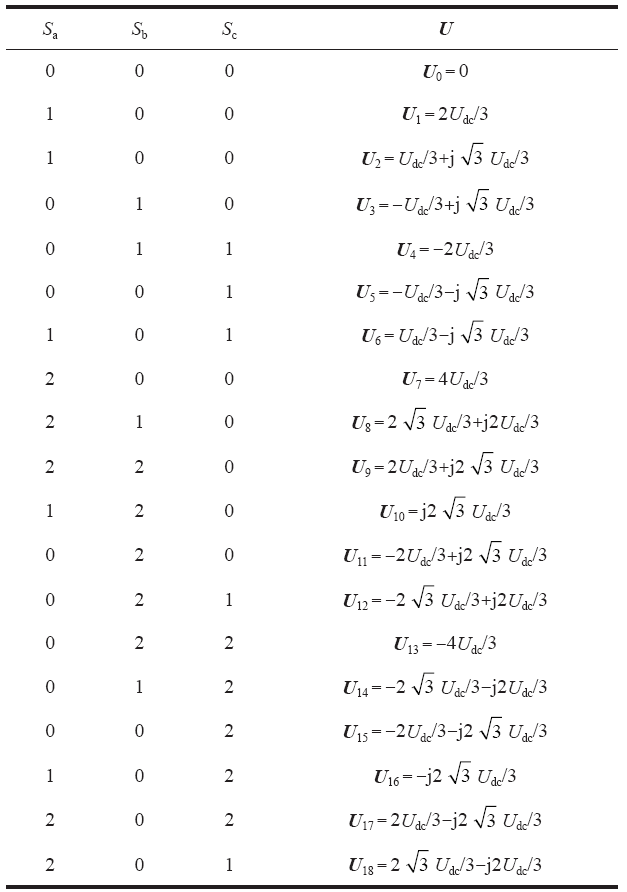
图2
2.2 负载模型
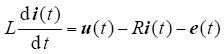
逆变器的三相输出电压的参考电位为电网中性点n。电阻和电感负载分别为R与L,逆变器产生的电压为u,产生的负载电流为i,对T型三电平逆变器的拓扑电路运用基尔霍夫定律,得到T型三电平逆变器系统满足以下状态方程[12]
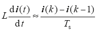
通过使用离散时间的负载电流来预测未来的值, 在一个采样周期Ts内,电流的变化率可以近似表示为
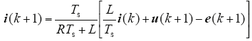
将式(6)带入式(5)中,得到离散时间之间的变量关系表示为
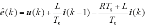
反电动势的当前和过去的估计值可以由式(5)对时间和负载测量电流的反向推移得到,即
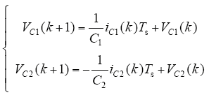
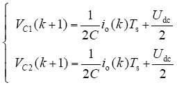
在T型三电平光伏并网逆变系统中,直流侧的两个分压电容分别为C1、C2,则预测电容电位计算式可表示为
2.3 中点电位不平衡的原因
(1)制作工艺有限,导致两电容参数不能完全一致,所以充放电不均匀,造成中点电位偏移。
(2)开关延迟。
(3)电网电流发生变化。
(4)功率因数会影响中点电位,无功电流分量会造成中点电位的周期性波动,有功电流分量会造成中点电位的偏移,并逐渐积累。
中点电位不平衡会给逆变器系统造成许多危害。并网时导致逆变器输出电压波形发生畸变,输出电压波形畸变还会加剧中点电位的不平衡;同时,会造成对开关器件的损坏;分压电容不停充放电,也缩短了使用寿命。因此,对中点电位的平衡控制十分关键。
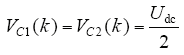
综合以上原因,考虑实现中点电位的平衡控制,则需要两个电容上的电压相等,则有
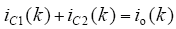
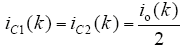
假设直流侧电容C1、C2中点的电流为io,则有
理想情况下,期望有C1 = C2 = C,假设该关系成立,则有如下关系式成立
由此可知,当直流电压源固定时,中点电位不平衡的主要原因是由中点电流值的大小决定的。假设中点电位的偏差值与中点电流有如下关系

根据式(14),综合生产实践,可知母线电容的容量不能设计为无穷大,且容量越大,成本越高。因此,当电容容量为一确定值时,通过减小中点电流值可实现中点电位的平衡控制。基于该思想,在传统的预测电流控制方法的基础上,设计性能指标函数,可以保证系统的动态平衡。
3 预测控制器设计
3.1 控制策略原理
本文的预测控制原理如图3所示。它通过预测变量的未来值对整个系统进行控制,其中的性能指标函数包含预测电流与参考电流之间的绝对误差和直流侧电容电压偏差。对性能指标函数进行优化,选择最优的开关状态,在下一个采样周期中将其作为逆变器的门极驱动信号,达到对逆变器的快速控制。
图3
3.2 控制算法的实现
根据模型预测控制的原理框图,其实现步骤如下:
(1)负载电流采样。模型预测控制器需要获得在第k时刻的负载电流值,采用三个电流传感器在三电平逆变器的负载端进行电流采样。
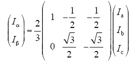
(2)坐标变换。为了简化计算,将采样电流从三相abc静止坐标系变换到两相αβ静止坐标系下,变换公式为
(3)中点电流的检测。采用电流传感器测量在k时刻的直流侧中点电流值,从而得到k时刻中点电位的偏差值。
(4)预测。采用式(7)获取k + 1时刻的负载电流预测值,该过程涉及到逆变器在第k个采样时刻的电压矢量和电流矢量。
(5)优化性能指标函数。考虑下一时刻的预测电流与参考电流之间的误差,以及直流侧中点电位的偏差,这两个因素构成的性能指标函数为

式中,iα和iβ是所测负载电流i的实部和虚部;iα*和iβ*是给定参考电流i*的实部和虚部;nc表示电容中点电位平衡的调节系数。采用平方误差的形式作为性能指标函数,可得到更好的电流跟踪效果。
(6)驱动逆变器。通过循环过程,选择使性能指标函数值最小的开关状态,作为门极驱动信号输入到逆变器,进入下一时刻的预测。
4 仿真及结果分析
为了验证基于模型预测控制的中点电位平衡控制方法,采用Matlab/Simulink进行仿真分析。搭建T型三电平逆变器模块,逆变器输出接RL负载,再与三相电网连接。模型预测控制方法通过嵌入Matlab程序实现。仿真参数设置为:直流侧电压源:520V;分压电容:4 700μF;负载端电阻:10Ω;电感:10mH;参考电流:正弦信号,幅值13A,频率50Hz;采样周期:100μs;仿真时间:0.1s。
图4
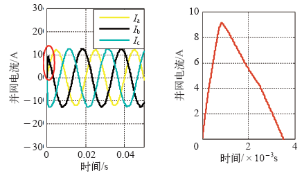
由图4可以看出,T型三电平逆变器的三相并网电流为光滑的正弦波,幅值约为13A,其中b相并网电流在0.8ms时达到稳定,a相与c相并网速度均比b相快,表明系统具有快速的动态响应。
图5
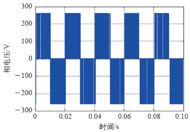
图6
图7
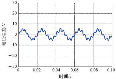
由图7可以看出,直流侧两个分压电容的电压差保持在0~±5V之间,波动幅值较小,呈现收敛趋势。证明了本文所采用的预测控制方法实现了中点电位的平衡控制。
图8所示为T型三电平逆变器的输出线电压波形。
图8
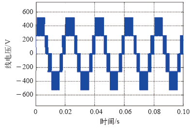
由图8可以看出,其输出表现优良,三电平工作模式明显,波形近似为正弦信号。
5 结论
本文研究了一种基于模型预测控制的T型三电平逆变器的控制方法,从T型三电平逆变器的电路拓扑出发,建立了数学模型,分析了影响中点电位不平衡的原因,详细设计了模型预测控制器。与传统方法相比,该方法具有如下特点:
(1)实现过程简单灵活,通过软件编程即可实现。
(2)动态响应速度快。根据系统的数学模型选择最优的开关状态,不需安装PWM调制器。仿真结果表明并网电流在0.8ms即达到稳定。
(3)能够对T型三电平逆变器进行中点电位的平衡控制,且能够输出高质量的波形。
参考文献
基于零序注入的NPC 三电平变流器中点电位反馈控制
[J].Output AC voltage compensation and neutral point voltage feedback control under neutral point voltage unbalanced conditions are discussed. A neutral point voltage feedback control strategy based on zero sequence injection is proposed. Using this strategy, not only output voltage can be guaranteed no distortion but also neutral point voltage can be adjusted at will. The modulation strategy is based on SPWM principal, so it’s very simple to realize, and suitable for enhancing traditional neutral point balance control or applications where need to control up and down DC link voltage separately. The neutral point current control ability of the strategy is given, and the neutral point voltage low frequency fluctuation problem is also analyzed. Simulation and experimental results verify the correctness of this theory.
Neutral point voltage feedback control based on zero sequence injection for NPC three-level converter
[J].Output AC voltage compensation and neutral point voltage feedback control under neutral point voltage unbalanced conditions are discussed. A neutral point voltage feedback control strategy based on zero sequence injection is proposed. Using this strategy, not only output voltage can be guaranteed no distortion but also neutral point voltage can be adjusted at will. The modulation strategy is based on SPWM principal, so it’s very simple to realize, and suitable for enhancing traditional neutral point balance control or applications where need to control up and down DC link voltage separately. The neutral point current control ability of the strategy is given, and the neutral point voltage low frequency fluctuation problem is also analyzed. Simulation and experimental results verify the correctness of this theory.
Comparison of a soft switched TCM T-type inverter to hard switched inverters for a 3 phase PV grid interface
[C].
不同零序电压注入的NPC 三电平逆变器中点电位平衡算法的比较
[J].中点箝位型(neutral point clamped,NPC)三电平逆变器已被广泛应用,中点电位的平衡是其关键技术之一。首先建立基于零序电压注入的中点电位的数学模型,然后根据模型分析采用三种不同零序电压注入的计算方法。在实验室搭建三电平并网逆变器实验样机,比较在不同功率因数下,3种不同零序电压注入方法的中点电位动稳态平衡能力。结果表明,3种方法均能很好地平衡中点电位。此外,在实际条件下,上下电容值常会不相等,因此有必要补充在上下电容值误差为12%条件下的实验。实验验证了3种不同零序电压注入方法在上下电容值误差较大时仍能很好地控制中点电位的平衡。
Comparisons of the neutral point voltage balancing algorithm for NPC three-level inverters based on different zero-sequence voltage injection
[J].中点箝位型(neutral point clamped,NPC)三电平逆变器已被广泛应用,中点电位的平衡是其关键技术之一。首先建立基于零序电压注入的中点电位的数学模型,然后根据模型分析采用三种不同零序电压注入的计算方法。在实验室搭建三电平并网逆变器实验样机,比较在不同功率因数下,3种不同零序电压注入方法的中点电位动稳态平衡能力。结果表明,3种方法均能很好地平衡中点电位。此外,在实际条件下,上下电容值常会不相等,因此有必要补充在上下电容值误差为12%条件下的实验。实验验证了3种不同零序电压注入方法在上下电容值误差较大时仍能很好地控制中点电位的平衡。
Predictive current control of a voltage source inverter
[J].
DOI:10.1016/j.isatra.2015.10.007
URL
PMID:26549566
[本文引用: 1]

Due to its fault tolerance, a multiphase brushless direct current (BLDC) motor can meet high reliability demand for application in electric vehicles. The voltage-source inverter (VSI) supplying the motor is subjected to open circuit faults. Therefore, it is necessary to design a fault-tolerant (FT) control algorithm with an embedded fault diagnosis (FD) block. In this paper, finite control set-model predictive control (FCS-MPC) is developed to implement the fault-tolerant control algorithm of a five-phase BLDC motor. The developed control method is fast, simple, and flexible. A FD method based on available information from the control block is proposed; this method is simple, robust to common transients in motor and able to localize multiple open circuit faults. The proposed FD and FT control algorithm are embedded in a five-phase BLDC motor drive. In order to validate the theory presented, simulation and experimental results are conducted on a five-phase two-level VSI supplying a five-phase BLDC motor.
一种改进型预测电流控制算法
[J].The final aim of the control system of grid-connected inverter is to track the reference current. So it is needed to predict the reference current according to the previous two or three switching periods. Due to the mismatch of the model inductance and actual inductance, the impact had on the stability of system for different control algorithms will be different, namely on the premise that the system be stable, different algorithm differs in the tolerance of inductance mismatch. On the basis of analyzing stability of single phase grid-connected inverter control system, advantages and disadvantages of each kind of predictive current control algorithms were compared. The fundamental reason why the control effects differed from each other was indicated. And an improved predictive current control algorithm was proposed that changes the aim of current error from the current difference of previous two periods to a specified one. The proximate calculation of intermediate variable is decreased and the stability of algorithm is improved. The tolerance of inductance dismatch is largely raised. Better stability margin is achieved relative to conventional methods. In the end the superiority is testified through simulation model and experimental platform.
An improved predictive current control algorithm
[J].The final aim of the control system of grid-connected inverter is to track the reference current. So it is needed to predict the reference current according to the previous two or three switching periods. Due to the mismatch of the model inductance and actual inductance, the impact had on the stability of system for different control algorithms will be different, namely on the premise that the system be stable, different algorithm differs in the tolerance of inductance mismatch. On the basis of analyzing stability of single phase grid-connected inverter control system, advantages and disadvantages of each kind of predictive current control algorithms were compared. The fundamental reason why the control effects differed from each other was indicated. And an improved predictive current control algorithm was proposed that changes the aim of current error from the current difference of previous two periods to a specified one. The proximate calculation of intermediate variable is decreased and the stability of algorithm is improved. The tolerance of inductance dismatch is largely raised. Better stability margin is achieved relative to conventional methods. In the end the superiority is testified through simulation model and experimental platform.
三相电压型逆变器模型预测控制
[J].
Model predictive control of three-phase voltage source inverter
[J].
模块化多电平变流器 HVDC 系统的模型预测控制
[J].DOI:10.7667/j.issn.1674-3415.2014.16.001 URL [本文引用: 1]
Model predictive control of modular multilevel converter for HVDC system
[J].DOI:10.7667/j.issn.1674-3415.2014.16.001 URL [本文引用: 1]
中点钳位型三电平并网逆变器有限集最优预测控制
[J].
DOI:10.7500/AEPS201209014
URL
[本文引用: 1]
A state space model for the neutral point clamped three-level grid-connected inverter is derived in detail,based on which a finite set optimal predictive(FSOP)control method is proposed.The proposed FSOP method is used to select the optimal switching vector from a finite set according to a cost function.The finite set is composed of27switching vectors,and the cost function is composed of the error of output current,the neutral point unbalanced voltage and the switching time of devices.The flow chart of FSOP control is given and the control performance is assessed by simulation and experiment.Experimental results show that the proposed FSOP method has a flexible control purpose,and the synthetic performance of the inverter can be optimized just by adjusting the weighting coefficients of factors in the cost function.FSOP control has bypassed the structure of controller plus modulator in the traditional control method and has a quick response in tracking the output current reference signals and balancing the neutral point voltage.
Three-level neutral point clamped inverter grid finite set of optimal predictive control
[J].
DOI:10.7500/AEPS201209014
URL
[本文引用: 1]
A state space model for the neutral point clamped three-level grid-connected inverter is derived in detail,based on which a finite set optimal predictive(FSOP)control method is proposed.The proposed FSOP method is used to select the optimal switching vector from a finite set according to a cost function.The finite set is composed of27switching vectors,and the cost function is composed of the error of output current,the neutral point unbalanced voltage and the switching time of devices.The flow chart of FSOP control is given and the control performance is assessed by simulation and experiment.Experimental results show that the proposed FSOP method has a flexible control purpose,and the synthetic performance of the inverter can be optimized just by adjusting the weighting coefficients of factors in the cost function.FSOP control has bypassed the structure of controller plus modulator in the traditional control method and has a quick response in tracking the output current reference signals and balancing the neutral point voltage.
基于复合模型预测控制策略的三电平APF研究
[J],
Research of three-level shunt APF control method based on composite model predictive control strategy
[J].
Design and implementation of a highly efficient three level T-type converter for low voltage applications
[J].
DOI:10.1109/TPEL.2012.2203151
URL
[本文引用: 1]
The demand for lightweight converters with high control performance and low acoustic noise led to an increase in switching frequencies of hard switched two-level low-voltage 3-phase converters over the last years. For high switching frequencies, converter efficiency suffers and can be kept high only by employing cost intensive switch technology such as SiC diodes or CoolMOS switches; therefore, conventional IGBT technology still prevails. In this paper, the alternative of using three-level converters for low-voltage applications is addressed. The performance and the competitiveness of the three-level T-type converter (3LT(2)C) is analyzed in detail and underlined with a hardware prototype. The 3LT(2)C basically combines the positive aspects of the two-level converter such as low conduction losses, small part count and a simple operation principle with the advantages of the three-level converter such as low switching losses and superior output voltage quality. It is, therefore, considered to be a real alternative to two-level converters for certain low-voltage applications.
基于双调制波技术的三电平Z 源逆变器中点电位平衡控制
[J].DOI:10.7667/j.issn.1674-3415.2013.07.015 URL [本文引用: 1]
Neutral-point potential balance control for three-level Z-source inverters based on double modulation wave technique
[J].DOI:10.7667/j.issn.1674-3415.2013.07.015 URL [本文引用: 1]
