

1 引言
对于导弹制导来说,如果能通过装载在导弹上的合成孔径雷达(Synthetic Aperture Radar,SAR)SAR获取目标或目标附近的典型地物地貌特征信息,形成实时图,并与预先准备好且存储在导弹中的基准图(含位置信息)进行图像匹配,从而控制导弹精确命中目标,则可大大提高导弹的攻击能力[1]。弹体的角运动和质心运动,以及外部载荷(如风、气流等)引起的扰动力矩会通过多种方式耦合到导引头天线上,严重影响天线的稳定与跟踪,为了实现可靠、高精度的目标跟踪,必须采用稳定平台来隔离弹体扰动[2]。在体积有限制的战术导弹应用中,为了消除弹体姿态变化对目标测量的影响,往往采用捷联稳定平台[3,4]来实现天线稳定。
当前应用较多的稳定平台是两轴转台,具有刚度大、结构紧凑、运动负荷小、精度高等优点。利用弹体惯导采集的数据,通过导线传输到稳定平台中,稳定平台根据位置关系进行坐标转换成平台转角。随着捷联控制技术的发展和研究的深入,针对捷联结构的构型、稳定解算、控制策略等方面的研究也越来越多,并出现了采用现代控制理论指导稳定平台位置闭环控制器的设计。本文介绍了捷联型稳定平台的工作原理及结构组成,建立了稳定平台系统的数学模型,在控制系统中引入了基于速度和加速度的前馈控制算法,并进行了相应的仿真研究。
2 捷联稳定平台的工作原理及组成
捷联末制导技术利用弹上捷联惯导的姿态信息,通过数学解算来稳定视线,捷联天线稳定平台是一种基于数学补偿的控制平台,其核心是数学稳定算法[5]。
在设计天线稳定平台时,采用方位、俯仰两自由度万向支架结构,天线安装在内框轴上,可以绕方位轴和俯仰轴运动。方位、俯仰通道均采用直流力矩电机加旋转变压器的直接驱动型式,驱动天线运转并形成速度与位置闭环控制。平台方位环可360°旋转,平台俯仰环因结构空间限制对角度范围进行机械限位和软件限位。天线稳定平台框架如图1所示。
图1
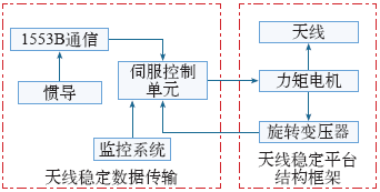
导弹惯导系统输出的位置、速度和姿态信息通过1553B总线传递给稳定平台控制系统。监控传递控制指令,CPU根据控制指令选择不同的工作模式,根据弹体姿态信息和控制指令传递过来的控制角度进行坐标正变换,转换成伺服平台的内框角和外框角。
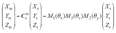
根据伺服平台结构安装特点,伺服平台由零位开始依次转动外框θy(绕Ys轴正向)、中框θz(绕Zs轴正向)、内框θx(绕Xs轴正向),则伺服平台坐标系与SAR测量坐标系间的转换矩阵为
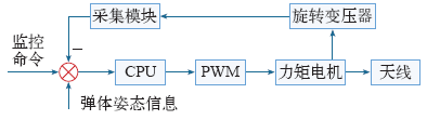
旋转变压器将采集的伺服平台当前位置信息和角度信息传递给CPU,CPU将坐标变换得到的角度与采集角度进行对比,将误差进行位置环PID运算和速度环PID运算,得到驱动电机电流,将电流值通过PWM传递给力矩电机,使得力矩电机驱动天线旋转到控制指令要求的位置。稳定平台控制系统简化框图如图2所示。
图2
3 双闭环PID控制算法
稳定平台用于驱动天线运转,实现波束指向随动,并隔离弹体姿态扰动稳定波束指向,稳定平台的控制精度直接影响SAR成像质量。本文采用直流力矩电机直接驱动天线转动,省去了减速机等环节,减少了结构误差带来的精度损失。
通常稳定平台控制系统结构由速度环和位置环两环组成,速度环用于提高稳定平台的运行平稳性,采用PI控制。位置环为稳定平台控制系统的最外环,用于快速准确跟踪给定位置,并对负载扰动和系统参数变化的影响具有很好的鲁棒性。双闭环控制系统示意图如图3所示。
图3
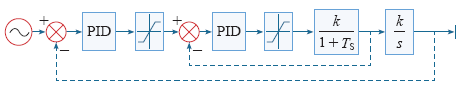
图3中,速度环传递函数可以写作
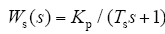
式中,Kp为放大系数;Ts为电路平均失效时间。
在PID控制中,将PID参数中微分时间设为0,设定比例增益积及积分时间,PID控制就成为了PI控制,比例增益Kp越大,系统调节时间越短,但系统稳定性越差,超调量越大。积分时间Ti的值越大,积分作用越弱,系统调节时间越长,越不容易超调。在本系统要求控制精度高、稳定时间短的情况下,采用普通PI控制时,要么系统超调量大、要么稳定时间长,不能满足系统设计要求。因此,在位置环采用分段PI控制,将角度误差根据范围分成8段,不同的误差选择不同的比例参数,这样可以提高系统的控制性能。
4 前馈补偿控制算法的应用
针对高精度伺服系统,采用基于偏差的PID闭环控制时,在无偏差量时PID控制器将无输出量,同时伴随系统延迟等因素的影响,无法更好地提高系统性能。为了提高系统的跟踪性能,需要输出完全复现输入,采用基于速度和加速度补偿的前馈控制。
图4
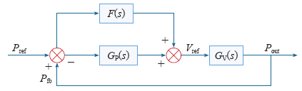
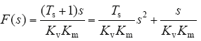
由式(3)可以看出,位置前馈函数由速度前馈函数和加速度前馈函数两部分组成。
速度和加速度前馈补偿涉及到两个方面,数据传输率及数据延时。惯导到伺服控制之间的数据传递具有延时不确定性,会影响伺服插值预估算法的准确性,从而影响伺服稳定精度。惯导到伺服之间的数据率较低,在频率较高时,角度、角速度和角加速度变化剧烈,对伺服稳定精度影响较大。为此,在惯导数据传输过程中,将惯导与伺服控制之间的数据率设置为800Hz,伺服控制电路中加入时间同步电路改善延时不确定性对伺服插值预估算法的影响,在伺服控制软件中根据时间来计算速度延时误差。前馈系统软件设计流程图如图5所示。
图5
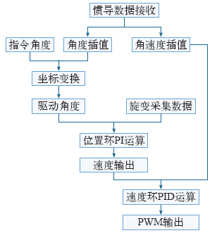
图5
基于前馈补偿算法的软件流程图
Fig.5
Software flow chart based on feed-forward compensation algorithm
5 试验结果及分析
图6
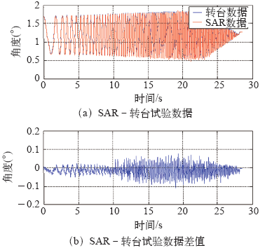
图7
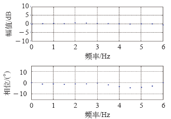
图8
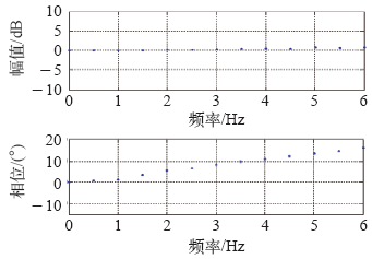
图8
插值后平台内框轴转角频率特性
Fig.8
Frequency characteristic of frame axis in platform after interpolation
根据图6的数据分析,在未进行前馈插值前,伺服内框轴转角的相位滞后转台约5°,幅值为-2~3dB;插值后,相位超前了约18°,幅值为-0~3dB;内框轴转角–惯导的跟踪误差小于0.1°时的概率为99.96% ,达到0.1°(3σ)。
6 结论
本文介绍了弹载捷联式稳定平台的工作原理及组成,在传统PID控制算法基础上,建立了分段PID控制的位置、速度双闭环控制系统,为提高控制精度,引入了基于速度和加速度的前馈补偿控制,提出数据传输率及时间误差对系统补偿的影响,拟制了软件控制流程图。通过试验分析,基于速度和加速度的双前馈双闭环控制系统,能有效提高稳定平台控制系统的响应速度和跟踪精度。
参考文献
弹载SAR脉冲重复频率设计研究
[J].
Design method of pulse repetition frequency of missile-borne side-looking SAR
[J].
捷联式天线平台动力学建模与仿真分析
[J].In space constrained tactical missiles, the size of seeker antenna servomechanism was restricted strictly, and rate gyroscope stabilization platform failed to work very well. The strapdown stabilization technique can be applied to stabilize line-of-sight(LOS). Based on configuration feature and stabilizing principle, a complete gimbal kinematics and dynamics model of two-degree-of-freedom strapdown antenna platform was achieved via coordinate transformation. The gimbal coupling characteristics was analyzed and simulated. Analysis indicates that main differences between strapdown stabilization platform and rate gyroscope stabilization platform lies in information obtaining and control mode. The rate gyroscope platform gets stability using hardware directly, while strapdown platform bases on software compensation. Simulating also shows that coupling between gimbals and missile body is strong, which need take effect measures to isolate. While cross coupling between outer gimbal and inner gimbal is weak, which can be ignored in practice. Results obtained will be a theoretical foundation for the further study of strapdown antenna platform, and it will be a engineering design suggestion for LOS stabilized system of miniaturized seeker.
Dynamics modeling and simulation analyzing for strap down antenna stable platform
[J].In space constrained tactical missiles, the size of seeker antenna servomechanism was restricted strictly, and rate gyroscope stabilization platform failed to work very well. The strapdown stabilization technique can be applied to stabilize line-of-sight(LOS). Based on configuration feature and stabilizing principle, a complete gimbal kinematics and dynamics model of two-degree-of-freedom strapdown antenna platform was achieved via coordinate transformation. The gimbal coupling characteristics was analyzed and simulated. Analysis indicates that main differences between strapdown stabilization platform and rate gyroscope stabilization platform lies in information obtaining and control mode. The rate gyroscope platform gets stability using hardware directly, while strapdown platform bases on software compensation. Simulating also shows that coupling between gimbals and missile body is strong, which need take effect measures to isolate. While cross coupling between outer gimbal and inner gimbal is weak, which can be ignored in practice. Results obtained will be a theoretical foundation for the further study of strapdown antenna platform, and it will be a engineering design suggestion for LOS stabilized system of miniaturized seeker.
Strapdown stabilization for imaging seekers
[J].
Direct versus indirect line of sight(LOS) stabilization
[J].DOI:10.1109/TCST.2002.806443 URL [本文引用: 1]
半捷联稳定控制方案与制导信息提取方法
[J].
New stabilization control and guidance information extract approach with a semi-strap-down structure
[J].
光电跟踪系统中的伺服控制技术
[J].
Servo control technologies in electro-optical tracking system
[J].
基于前馈补偿的并联型光电设备稳定平台伺服控制
[J].
DOI:10.1016/j.ajo.2019.12.015
URL
PMID:31883465
[本文引用: 1]

Limited information is available on morphological and functional regeneration of photoreceptors after retinal detachment (RD) surgery. This observational clinical study compared morphological and functional changes of cones after vitrectomy for macula-off retinal detachment. DESIGN PROSPECTIVE: fellow-eye comparative case series METHODS STUDY POPULATION: Five eyes after vitrectomy with gas for macula-off retinal detachment (retinal detachment eyes, RDE) and five healthy fellow-eyes (HFE) of five patients (mean age 59.8 years, macula-off duration 0.5 days to 5.5 days) OBSERVATION PROCEDURES: Eyes were examined with AO-OCT, spectral domain OCT (SD-OCT) and microperimetry (MP) at 6 (baseline, BL) and 56 weeks (follow-up, FUP) after 23 gauge pars-plana vitrectomy and SF6 gas tamponade. Eight corresponding regions at foveal eccentricities of 2.5° (ecc 2.5) and 6.5° (ecc 6.5) were analysed in every eye. AO-OCT en-face images and SD-OCT B-Scans were graded regarding irregularity and loss of photoreceptor signals ranging from none to severe changes. The number of detectable cones at height of the inner-outer segment junction (IS/OS) and cone outer segment tips (COST) was counted manually in AO-OCT images. MP with a custom grid was used to assess retinal sensitivity at these locations.
Parallel photo electrical-device stabilization platform servo control based on feedforward compensation
[J].
DOI:10.1016/j.ajo.2019.12.015
URL
PMID:31883465
[本文引用: 1]
Limited information is available on morphological and functional regeneration of photoreceptors after retinal detachment (RD) surgery. This observational clinical study compared morphological and functional changes of cones after vitrectomy for macula-off retinal detachment. DESIGN PROSPECTIVE: fellow-eye comparative case series METHODS STUDY POPULATION: Five eyes after vitrectomy with gas for macula-off retinal detachment (retinal detachment eyes, RDE) and five healthy fellow-eyes (HFE) of five patients (mean age 59.8 years, macula-off duration 0.5 days to 5.5 days) OBSERVATION PROCEDURES: Eyes were examined with AO-OCT, spectral domain OCT (SD-OCT) and microperimetry (MP) at 6 (baseline, BL) and 56 weeks (follow-up, FUP) after 23 gauge pars-plana vitrectomy and SF6 gas tamponade. Eight corresponding regions at foveal eccentricities of 2.5° (ecc 2.5) and 6.5° (ecc 6.5) were analysed in every eye. AO-OCT en-face images and SD-OCT B-Scans were graded regarding irregularity and loss of photoreceptor signals ranging from none to severe changes. The number of detectable cones at height of the inner-outer segment junction (IS/OS) and cone outer segment tips (COST) was counted manually in AO-OCT images. MP with a custom grid was used to assess retinal sensitivity at these locations.
