

1 引言
近十多年来,我国电力工业在直流输电工程建设的应用和研究方面取得了长足的发展和进步。随着向家坝–上海、锦屏–苏南和哈密南–郑州等一系列的±800kV特高压直流输电工程的相继投运,截止到2014年,我国共有33个投运和在建的直流输电工程。
目前,我国受端换流站落点位于经济发达地区,人口密度大,电网结构复杂,地下金属设施众多,传统的常规接地极设计方式下选址工作变得越来越困难,因此有必要开展由数个位于不同地区的子接地极(简称子极)通过馈流线路实现子极之间相连和换流站接地线路接入的接地系统的研究,这种接地极即为分布式直流接地极,在定义上有别于常规接地极和共用接地极。目前对直流极的研究集中在极址勘探[1,2]、接地极设计[3,4,5,6,7,8,9,10,11,12,13,14,15]、接地极温升计算和试验[16,17,18,19,20,21,22]及直流极对交流电网内变压器的不利影响[23,24,25]等方面,但针对分布式接地极的系统研究并不多[26],在其工作原理、仿真模型和效果评估方面的研究存在一些困难。本文将对分布式接地极的工作原理、设计原则、仿真模型及应用效果等进行逐一分析。
2 分布式接地极的原理和特点
分布式直流接地极由分布于电网覆盖地理区域的多个子接地极组成,各子接地极通过优化方法选定,再通过特定接线方式把所有的子接地极连接起来,形成多个直流输电工程公用的分布式接地极。除满足这一区域内所有直流输电工程对接地极的要求外,还可以避免直流电流过度集中,均衡地表电位,从而从根本上缓解直流偏磁风险。
分布式接地极的设计和建设也可以避免新建接地极的征地问题,实现资源优化配置且更好地适应未来直流输电工程建设的需要。分布式接地极还可以提升接地极性能,如降低接地电阻、跨步电势和接触电势,缓解接地极发热问题和接地极入地电流对埋地金属的腐蚀影响。
随着我国直流输电工程的大量建设,送端和受端系统存在多个直流落点,直流入地电流对交流系统的影响越来越严重。在此背景下,分布式接地极具有十分广阔的应用前景。分布式接地极一旦建成,新建直流输电工程一般无需增加直流接地极,可以降低直流极选址难度,减小接地极的征地成本,更有利于改善直流极的接地和温升特性,降低直流电流对环境的影响,降低交流电网变压器直流偏磁风险。
3 分布式接地极的建模仿真
3.1 分布式接地极的完整模型
分布式接地极的理论模型可以参考场路结合的节点电压法[27]。其仿真模型较传统的直流接地极仿真模型要复杂,它与传统模型的不同之处在于:①地下存在大范围分布的接地导体,需要使用大范围的地下电阻率;②由于地上馈流网络的存在,需要在接地模型中考虑馈流网络的传导作用。分布式接地极模型的节点电位模型
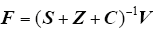
式中,S为支路散流电导阵,求解方法参见文献[8,13];Z和C分别是接地网导体的支路和馈流线路电导阻矩阵。
由于注入节点电流向量F已知,通过式(1)就可以很方便地求出节点电压向量V,这样分布式接地极的等效接地阻抗、跨步电势、地表电位分布和空间电流分布等问题都可以解决。
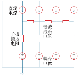
3.2 分布式接地极的模型简化
图1

由节点电压法有
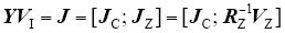
式中,VI为电流注入后子接地极的电压列向量;VZ为子极地耦合电位列向量。
其中

式中,MZ为子极间的互阻矩阵;IZ为子极的入地电流列向量。
由IZ的定义有
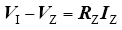
式中,IZ为子极的入地电流列向量;RZ为子接地极的接地电阻。
由于MZ、Y、IZ和RZ已知,故联立式(3)~式(5)即可求得分布式接地极的相关参数。在这样的情况下,分布式接地极的模型可以大大简化。
3.3 分布式接地极的纯电路模型
在简化模型的基础上,进一步删去图 1中的耦合电位量,分布式接地极的模型就简化成纯电路模型。删去耦合电位量可能会造成一定的计算误差。当然,误差是否可接受取决于子极间互阻与子极接地电阻的比值,如果比值很小,则忽略耦合电位可以简化计算模型;如果比值较大,则不能忽略。
3.4 算例
假设某分布式接地极的示意图如图2所示。图 中,分布式接地极由4个子极组成,子极成直线型布置,相邻子极距离20km,由馈流系统的线路连接起来。子极由4根长100m的接地导体构成,按十字形排列,埋深取4m。子极导体采用直径70mm的高压硅铸铁(电阻率取1.7×10⁻⁷Ω·m),布置在截面积为1.1m×1.1m的焦炭床之中(电阻率取0.2Ω·m)。馈流系统的线路取架空的35kV线路,线路电阻为0.01Ω/km,线路连接相邻的子极的电流注入点。
图2
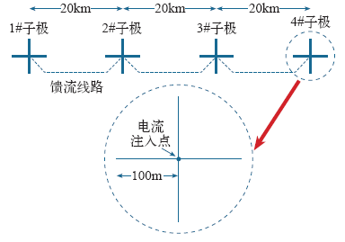
表1 广东鱼龙岭极址水平10层土壤的参数
Tab.1
| i | ρi /(Ω·m) | hi /m |
|---|---|---|
| 1 | 70 | 6 |
| 2 | 120 | 25 |
| 3 | 90 | 60 |
| 4 | 220 | 300 |
| 5 | 500 | 500 |
| 6 | 2 500 | 3 500 |
| 7 | 34 385 | 13 100 |
| 8 | 5 324 | 17 100 |
| 9 | 83 095 | 97 600 |
| 10 | 813 | ∞ |
表2 湖北宜昌地区水平十五层土壤的参数
Tab.2
| i | ρi /(Ω·m) | hi /m |
|---|---|---|
| 1 | 100.00 | 10.00 |
| 2 | 300.00 | 50.00 |
| 3 | 48.99 | 415.39 |
| 4 | 5.61 | 702.82 |
| 5 | 241.43 | 2 160.02 |
| 6 | 37.37 | 2 246.79 |
| 7 | 61.77 | 3 762.22 |
| 8 | 110.97 | 5 007.95 |
| 9 | 303.23 | 3 874.73 |
| 10 | 36.11 | 5 763.70 |
| 11 | 474.09 | 5 450.66 |
| 12 | 973.07 | 6 413.89 |
| 13 | 5 008.23 | 9 785.49 |
| 14 | 1 312.71 | 13 508.46 |
| 15 | 10.30 | ∞ |
| 电流注入点 | 模型 | ||
|---|---|---|---|
| 完整 | 简化 | 电路 | |
| 1#子极 | 0.342 6 | 0.343 3 | 0.307 3 |
| 2#子极 | 0.283 0 | 0.282 9 | 0.244 3 |
| 电流注入点 | 模型 | ||
|---|---|---|---|
| 完整 | 简化 | 电路 | |
| 2#子极 | 0.239 4 | 0.239 4 | 0.239 6 |
表5 入地电流的计算结果(表1电阻率和1#子极电流注入情况下)
Tab.5
| 电流注入点 | 入地电流/A |
|---|---|
| 1#子极 | 1 298.7 |
| 2#子极 | 766.2 |
| 3#子极 | 510.8 |
| 4#子极 | 429.3 |
经算例对比分析后,本文推荐使用简化模型对分布式接地极作仿真计算,在计算取得各子极的入地电流后再开展子极温升发热、跨步电势和其对环境影响的评估。
4 分布式接地极的选址优化
4.1 分布式接地极的选址优化方法
粒子群算法(Particle Swarm Optimization,PSO)是无导数方法,它通过群体中个体之间的协作和信息共享来寻找最优解,是一种基于群体智能的优化计算方法,粒子群算法存在局部搜索精度不足和“早熟”收敛的缺点。为了弥补粒子群算法的不足,改进算法的性能,对粒子群算法加入混沌算子。
混沌算子具有随机性、遍历性和规律性的特点。在每次循环的末尾加入混沌算子对最优解进行处理,可以增强粒子群算法的局部搜索能力。
PSO算法中粒子的运动以定向移动和随机搜索进行:每个粒子向当前所有粒子的最优解g*和自身最优解x*i移动,而且在移动的过程中对粒子附近位置作随机搜索。如果一个粒子找到比自身当前最优解更好的位置,则更新其当前最优解;如果当前全局最优解优于过往的全局最优解,则作替换。
设x*i为粒子i的当前最佳位置,全局最优解g*≈min f (xi),i = 1, 2, ..., np。np为粒子数量,混沌PSO的算法流程如下:
第1步:定义目标函数。例如,将系统内变压器磁动势平均值最小作为目标函数。自变量p = (x,y),代表新建直流接地极或变电站的坐标。
第2步:混沌初始化。按照式(6)和式(7)进行混沌初始化[28]
式中,ch1是(0,1)内的随机数。式(7)称为混沌映射[29],把混沌序列映射到参数规定的范围内,作为粒子的起始位置,粒子的起始速度一般设为0,并取得起始的全局最优解g* = min[ f (p1), ⋯,
f (pn)]。
第3步:t = t + 1,对所有np个粒子,使用式(8)产生新的速度vti,然后按式(9)更新粒子位置,并计算每个粒子的目标函数,更新每个粒子的最优位置x*i,并取得当前的全局最优解g*。
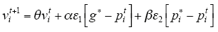
式中,pi和vi分别为粒子i的速度和位置;θ为惯性权重,其作用是保持粒子运动的惯性,使算法具有扩展搜索空间的趋势并有能力探索新的区域,θ∈[0.5,0.9],本文取θ = 0.7;ε1和ε2是两个2维的0~1之间的随机向量;x⊙y=[xi yi],α和β为加速系数,一般情况下α = β = 2。另外,vi可能任意取值,但在实际中应设置速度的上下限来防止发散,速度的上下限一般按照元素区间范围来设定。每次更新位置后得出的最优位置与全局最优值比较,更新全局最优值,记为globalbest。
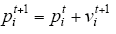
第4步:开始局部混沌搜索算子。混沌搜索循环搜索hd次。每次循环开始按式(6)产生nl个混沌序列chi,作为局部混沌搜索算子,对globalbest按式(10)进行混沌载波。
式中,i = 1, 2, …, hd。每次循环末尾,判断x′j中的最优值是否优于globalbest,如果是,则用其替代globalbest。
第5步:若目标函数不再减少或者超出迭代次数,则输出结果,否则t = t + 1,转入第3步。
4.2 分布式接地极的优化选址算例
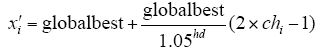
以下用浙江电网的实际情况来说明本文方法在新建直流接地极与变电站寻址中的作用。浙江电网2014年的电网地理信息接线图如图3所示。图中,黑色加点表示500kV和220kV变电站和发电厂,直线表示不区分回数的输电线路。
图3
假设浙江电网直流输电工程需要4个子接地极,根据征地以及规划初步限定极址在经纬度(119.40E,28.60N),(120.00E,28.60N),(120.00E,29.00N),(119.40E,29.00N)的区域内。直流接地极入地电流5 000A,接地电阻0.1Ω,埋深3m,4个子极按照地理位置顺序相连。运用本文方法对接地极极址进行优化计算,优化目标为系统内变压器的平均直流磁动势最小。变压器的磁动势MMF可按不同变压器绕组结构写成如下形式:
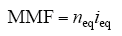
单相变压器
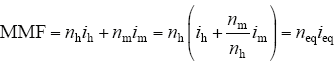
对普通三绕组变压器
对自耦变压器
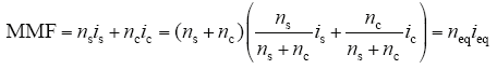
式中,nh、nm、ns和nc分别是普通三卷式变压器的高压和中压绕组的匝数、自耦变的串联绕组和公共绕组的匝数;neq和ieq为流经变压器的等效绕组匝数和等效直流电流。直流电流分量i的含义与n的含义近似,在此不再赘述。
本文推荐系统内变压器的平均直流磁动势作为新建直流极与变电站选址的优化约束条件,在计算取得新建直流极与变电站的最佳选址后再开展对整个交流电网各变电站直流偏磁风险的计算和评估。
由于子极地理分布的分散性,分布式接地极在接地参数方面可以取得良好的应用效果,其接地电阻更小,相对使用的接地材料更少,不过馈流系统的建设增加了部分费用。
表6 分布式直流极使用前后变压器绕组电流(单位:A)
Tab6
| 变压器类型/kV | 使用前 | 使用后 | 优化后 |
|---|---|---|---|
| 500 | 5.917 4 | 5.044 7 | 4.839 6 |
| 220 | 49.095 6 | 22.901 4 | 20.049 8 |
由于分布式接地极子极比较分散,地表电位局部集中的问题得到一定程度上的改善,所以直流电流分布区域更加分散,靠近直流极的变压器绕组上的直流电流幅值也大大下降。而优化选址后的子极分布进一步均衡了大范围地表电位,改善了直流电流的分布。
分布接地极可以有效地降低直流输电入地电流对交流电网内变压器的直流偏磁危害,特别是在多回直流输电同时单极大地运行的情况下,有50%的概率出现正负电流在馈流系统上抵消的情况,此时入地电流大大下降。而本文的子极优化选址方法可以增进分布式接地极的作用和效果,进一步均衡地表电位,降低变压器绕组上的直流电流幅值。
5 讨论
随着交直流特高压工程的深入推进,直流输电工程越来越多且容量越来越大,多个分散的独立接地极会造成严重的区域性直流偏磁问题。
通过理论分析和建模仿真等手段,证明了分布式接地极在技术上的可行性。但目前分布式接地极还是存在子极间地理位置配合等经济性问题。
分布式接地极还可以使用灵活的子接地极投切策略,从而主动调整地下电流场的分布以适应不同的运行工况。一般情况下,子极全部投入方式工作性能是最好的,其入地电流的分配最均衡。但如果考虑到子极运行到设计年限后更换接地导体和子极搬迁极址的问题,子接地极投切功能还是很有必要的。
6 结论
(1)提出了分布式直流接地极的构想,分布式直流接地极可以提升接地极性能和均衡直流电流分布,从根本上缓解直流偏磁风险和新建接地极的征地问题。
(2)研究了三种分布式接地极的仿真模型:完整的接地仿真模型、简化模型和纯电路模型。用实例分析了三种模型的区别,完整的计算模型和简化计算模型可以取得完全一致的结果,而纯电路模型由于忽略互阻影响,存在明显误差。
(3)提出了基于全局最优位置混沌粒子群优化算法的直流极选址优化办法,并以浙江电网为例,对比了不采用分布式接地极、采用分布式接地极以及优化后的分布式接地极三种方法的变压器绕组电流,证明了分布式接地极以及选址优化后的分布式接地极对降低变压器绕组直流偏磁电流效果明显。
(4)目前我国传统的直流接地极已经出现应用瓶颈,本文以浙江电网为例说明了分布式接地极的实际应用方案,并分析了分布式接地极的电流分布、对交流电网内变压器直流偏磁的缓解作用和对环境的影响,为分布式接地极的应用提供参考。
参考文献
Measurements and computa-tions of the performance of grounding systems buried in multilayer soils
[J].DOI:10.1109/61.97681 URL [本文引用: 1]
Proper grounding of on site electrical power systems
[J].DOI:10.1109/2943.911190 URL [本文引用: 1]
任意块状结构土壤中接地的边界元法分析
[J].To calculate and analyze the grounding system in the soil with arbitrary massive texture, according to the principle of boundary element analysis a general algorithm is proposed and the principle as well as calculation formulae of the proposed algorithm are presented in detail. In the proposed algorithm, the potentials of boundary surface elements and the potential gradients of conductor element are unknown numbers, the linear equations are listed and solved by the given algorithm to attain all parameters of grounding system. By use of Matlab, a simple grounding system in the soil with massive texture model is modeled and calculated, and the comparison of the calculated result with that by CDEGS software shows that the biggest relative error of the grounding resistance is 1.266% and the average error of the surface potential is 4.278%, thus the proposed method is correct. In allusion to the model of hathpace that often appears in practice, the calculation results by general algorithm are given and the occasion of adding vertical grounding electrodes to hathpace model to reduce grounding resistance is analyzed and calculated. Results of calculation examples show that the proposed method possesses higher calculation efficiency and can be applied in the calculation and analysis of arbitrary grounding models in the soil with arbitrary massive texture.
Boundary element analysis on grounding systems in soil with arbitrary massive texture
[J].To calculate and analyze the grounding system in the soil with arbitrary massive texture, according to the principle of boundary element analysis a general algorithm is proposed and the principle as well as calculation formulae of the proposed algorithm are presented in detail. In the proposed algorithm, the potentials of boundary surface elements and the potential gradients of conductor element are unknown numbers, the linear equations are listed and solved by the given algorithm to attain all parameters of grounding system. By use of Matlab, a simple grounding system in the soil with massive texture model is modeled and calculated, and the comparison of the calculated result with that by CDEGS software shows that the biggest relative error of the grounding resistance is 1.266% and the average error of the surface potential is 4.278%, thus the proposed method is correct. In allusion to the model of hathpace that often appears in practice, the calculation results by general algorithm are given and the occasion of adding vertical grounding electrodes to hathpace model to reduce grounding resistance is analyzed and calculated. Results of calculation examples show that the proposed method possesses higher calculation efficiency and can be applied in the calculation and analysis of arbitrary grounding models in the soil with arbitrary massive texture.
高压直流输电接地极溢流特性
[J].为研究接地极型式参数和土壤结构对溢流特性及接地性能的影响规律,考虑电极自阻及多点并联注流方式,建立了基于线电流法的场路耦合模型,对圆环形直流接地极地电流溢流进行计算,并对地电位进行求解,然后通过与实测数据及软件建模仿真结果进行对比,验证了该方法的准确性和可行性。研究结果表明:外环半径一定时,极环数增加,接地极的溢流能力降低,接地电阻下降程度趋缓;分流比与环径比近似成正比,内环半径增大时,外环对内环的屏蔽作用先增强后减弱;上层土壤电阻率小于下层土壤电阻率时,上层土壤厚度增大,内外环分流比先减小后增大,上层土壤电阻率大于下层土壤电阻率时,分流比的变化趋势相反;同时,随着上层土壤厚度的增加,上层土壤电阻率对接地性能的影响增强,而下层土壤电阻率产生的影响减弱。
Current overflow characteristics of earth electrodes for HVDC transmission system
[J].为研究接地极型式参数和土壤结构对溢流特性及接地性能的影响规律,考虑电极自阻及多点并联注流方式,建立了基于线电流法的场路耦合模型,对圆环形直流接地极地电流溢流进行计算,并对地电位进行求解,然后通过与实测数据及软件建模仿真结果进行对比,验证了该方法的准确性和可行性。研究结果表明:外环半径一定时,极环数增加,接地极的溢流能力降低,接地电阻下降程度趋缓;分流比与环径比近似成正比,内环半径增大时,外环对内环的屏蔽作用先增强后减弱;上层土壤电阻率小于下层土壤电阻率时,上层土壤厚度增大,内外环分流比先减小后增大,上层土壤电阻率大于下层土壤电阻率时,分流比的变化趋势相反;同时,随着上层土壤厚度的增加,上层土壤电阻率对接地性能的影响增强,而下层土壤电阻率产生的影响减弱。
考虑土壤非线性的接地网有限元分析
[J].
Analysis of grounding grid by finite element method in consideration of soil nonlinear characteristics
[J].
A novel mathematical modeling of grounding system buried in multilayer Earth
[J].DOI:10.1109/TPWRD.2006.875857 URL [本文引用: 2]
Calculation of electric field and potential distributions into soil and air media for a ground electrode of a HVDC system
[J].DOI:10.1109/TPWRD.2003.809741 URL [本文引用: 1]
Analysis of the toroidal HVDC grounding systems in horizontal multilayer soils
[J].DOI:10.1109/TMAG.2006.871456 URL [本文引用: 1]
Design considera-tions of HVDC grounding electrodes
[C].
地形结构及参数对特高压直流地电流散流特性的影响分析
[J].
Influence of terrain structure and parameter on the divergence character of UHVDC grounding current
[J].
直流接地极结合均流系统的计算模型与求解
[J].
Calculation model and aolving method of HVDC grounding electrode with average-current system
[J].
特高压直流输电系统多换流站共用两个接地极的优化设计(英文)
[J].
Optimized design method of sharing two grounding electrodes by multi UHVDC converter stations
[J].
4个直流输电工程共用1个接地极运行方式的研究
[J].
Study on four HVDC systems sharing a common ground electrode
[J].
Influence of coke bed on HVDC grounding electrode heat dissipation
[J].DOI:10.1109/TMAG.2008.915872 URL [本文引用: 1]
±800kV圆环接地极电流场温度场耦合计算
[J].It is very complex to calculate current field and temperature field of DC grounding electrode. At first, based on coupling method of electric field and circuit, this paper computes current field of ±800kV cirque grounding-electrode on the condition of self-resistance of electrode. Then, the result of current field is considered as a boundary condition to compute temperature field of the electrode by 3-D finite element method. In order to verify the validity of the method, an engineering case is compared with calculation results. In addition, based on the computation method, the paper researches grounding performance of different cirque electrode on the condition of same electrode length, and gives some reference suggestions to practical engineering. Afterwards, a series of influencing factors of grounding performance are analyzed such as soil resistivity, embedded depth of electrode, and so on.
Coupling calculation of current field and temperature field of ±800kV cirque DC grounding-electrode
[J].It is very complex to calculate current field and temperature field of DC grounding electrode. At first, based on coupling method of electric field and circuit, this paper computes current field of ±800kV cirque grounding-electrode on the condition of self-resistance of electrode. Then, the result of current field is considered as a boundary condition to compute temperature field of the electrode by 3-D finite element method. In order to verify the validity of the method, an engineering case is compared with calculation results. In addition, based on the computation method, the paper researches grounding performance of different cirque electrode on the condition of same electrode length, and gives some reference suggestions to practical engineering. Afterwards, a series of influencing factors of grounding performance are analyzed such as soil resistivity, embedded depth of electrode, and so on.
特高压共用接地极热参数分析
[J].
UHVDC common ground electrode thermal parameters analysis
[J].
特高压直流输电圆环型接地极电流场计算
[J].
Current field cvalculation of cirque UHVDC transmission grounding electrode
[J].
垂直型直流接地极暂态温升计算与试验
[J].垂直型直流接地极可以有效解决极址选择困难问题,但也将带来土壤温升过高,接地极散流不均匀等难题。为了对接地极运行时的暂态温升进行有效计算,建立了暂态温度场计算模型,并通过试验进行验证。计算首先基于场路耦合法,在考虑接地极自阻的情况下对接地极电流场进行计算,然后将电流场计算结果作为温度场的计算条件,依据Gurtin变分原理构造时空有限元模型,对接地极进行暂态温升计算。试验选取长9 m、直径为30 mm的圆钢作为接地极,加载113 h的直流电流,分别采用热电偶传感器和霍尔电流传感器采集并记录接地极的温升规律以及散流特性。对比分析表明,计算结果与试验结果具有较高的吻合度,验证了算法的有效性,能为实际工程设计提供参考。
Test and computation for vertical ground electrode's transient temperature rise
[J].垂直型直流接地极可以有效解决极址选择困难问题,但也将带来土壤温升过高,接地极散流不均匀等难题。为了对接地极运行时的暂态温升进行有效计算,建立了暂态温度场计算模型,并通过试验进行验证。计算首先基于场路耦合法,在考虑接地极自阻的情况下对接地极电流场进行计算,然后将电流场计算结果作为温度场的计算条件,依据Gurtin变分原理构造时空有限元模型,对接地极进行暂态温升计算。试验选取长9 m、直径为30 mm的圆钢作为接地极,加载113 h的直流电流,分别采用热电偶传感器和霍尔电流传感器采集并记录接地极的温升规律以及散流特性。对比分析表明,计算结果与试验结果具有较高的吻合度,验证了算法的有效性,能为实际工程设计提供参考。
水平型直流接地极温升试验与仿真
[J].
Test and simulation for horizontal ground electrode's temperature rise
[J].
Controlled large-scale tests of practical grounding electrodes, part II: comparison of analytical and numerical predictions with experimental results
[J].
DOI:10.1109/TPWRD.2014.2298358
URL
[本文引用: 1]

This paper presents tests carried out at an outdoor experimental facility, described in the companion Part 1 paper, to investigate the performance of practical grounding systems. Here, the results of low-voltage dc, ac, and impulse tests performed on rod and grid electrodes are described, and the measured quantities are compared with computed values obtained from numerical models. Measured ground resistance and impedance at low frequency (including power frequency) showed reasonable agreement with simple standard formulae and computational models, but revealed a significant falloff with current magnitude in the range often used for practical testing of high-voltage grounding systems. This may have implications for the specifications of grounding test equipment and extrapolation of measured ground resistance/impedance at low-voltage/current to values representative of realistic fault currents. A frequency dependence of ground impedance was also measured. Specifically, a fall in impedance over a frequency range up to 100 kHz is not generally accounted for in grounding models.
直流大地运行时交流系统直流电流分布的预测方法
[J].
Estimation of DC current distribution in AC power system caused by HVDC transmission system in ground return status
[J].
复合土壤模型下HVDC系统单极大地运行时的电流分布
[J].土壤结构模型决定了HVDC接地极极址选择、布置形式和地表电位的分布,对分析HVDC单极运行对变压器产生的影响有重要作用。该文利用土壤水平分层和垂直分层后的格林函数,通过镜像法,根据其物理意义推导出在复合分层土壤结构中地表电位的解析公式。海洋在面积上远大于陆地,电阻率很小,对地表电位有影响,会降低靠近海洋附近土壤的电位。根据复合土壤模型和交流电网模型计算得到变压器中性点流过的直流电流,和实测值相符合。靠近海洋层的地表电位受到海洋的影响将下降至接近零电位,导致更多的直流电流从靠近海洋的变压器中性点流出,影响了变压器的正常运行。
DC currents distribution in HVDC systems of monopolar operation With ground return in complex soil structure
[J].土壤结构模型决定了HVDC接地极极址选择、布置形式和地表电位的分布,对分析HVDC单极运行对变压器产生的影响有重要作用。该文利用土壤水平分层和垂直分层后的格林函数,通过镜像法,根据其物理意义推导出在复合分层土壤结构中地表电位的解析公式。海洋在面积上远大于陆地,电阻率很小,对地表电位有影响,会降低靠近海洋附近土壤的电位。根据复合土壤模型和交流电网模型计算得到变压器中性点流过的直流电流,和实测值相符合。靠近海洋层的地表电位受到海洋的影响将下降至接近零电位,导致更多的直流电流从靠近海洋的变压器中性点流出,影响了变压器的正常运行。
直流接地极对电气化铁路的电磁影响
[J].
Electromagnetic influences of ground electrode on electrified railway
[J].
广域接地极方案初步研究
[J].
Primary research on HVDC WAN grounding electrode
[J].
Frequency-dependent grounding system calculation by means of a conventional nodal analysis technique
[J].DOI:10.1109/61.772327 URL [本文引用: 2]
基于排名映射概率的混沌人工蜂群算法
[J].
Chaotic artificial bee colony algorithm based on rank mapping probability
[J].
基于混沌局部搜索算子的人工蜂群算法
[J].
DOI:10.3724/SP.J.1087.2012.01033
URL
[本文引用: 1]
In order to improve the ability of Artificial Bee Colony (ABC) algorithm at exploitation, a new Chaos Artificial Bee Colony (CH-ABC) algorithm was proposed for continuous function optimization problems. A new chaotic local search operator was embedded in the framework of the new algorithm. The new operator, whose search radius shrinks with the evolution generation, can do the local search around the best food source. The simulation results show that: compared with those of ABC algorithm, the solution quality and the convergence speed of the new algorithm are better for Rosenbrock and the convergence speed of the new algorithm is better for Griewank and Rastrigin.
Artificial bee colony algorithm based on chaos local search operator
[J].
DOI:10.3724/SP.J.1087.2012.01033
URL
[本文引用: 1]
In order to improve the ability of Artificial Bee Colony (ABC) algorithm at exploitation, a new Chaos Artificial Bee Colony (CH-ABC) algorithm was proposed for continuous function optimization problems. A new chaotic local search operator was embedded in the framework of the new algorithm. The new operator, whose search radius shrinks with the evolution generation, can do the local search around the best food source. The simulation results show that: compared with those of ABC algorithm, the solution quality and the convergence speed of the new algorithm are better for Rosenbrock and the convergence speed of the new algorithm is better for Griewank and Rastrigin.
