


1 引言
随着分布式电源并网功率的增加,提升并网逆变器的容量及效率成为研究热点。在多级并网结构中,可采用高压串联和低压并联的电路[1],为减小高压逆变器的电流,也可采用模块化逆变器直接并联结构。然而,大功率的分布式电源输出功率具有随机性和波动性,在系统额定容量固定的情况下,容易造成逆变器的过载或轻载,影响其工作性能。当传输功率过高时,器件易因过电压、过电流而受损;当传输功率过低时,逆变器工作于低功率区间,会导致效率下降。
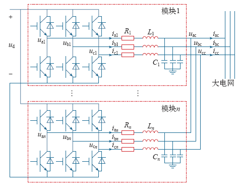
本文采用多模块化逆变器直接并联的结构,利用其灵活多变的组合形式,应对高压微网中大功率分布式电源出力的随机波动,如图1所示。首先建立单台逆变器的等效模型,分析传输功率与工作效率之间的内在规律,确定效率最佳工作区间;再针对逆变系统传输功率的变化情况,制定基于模糊控制理论的直接并联逆变模块投切控制策略,保证系统始终工作在安全、高效的功率区间;同时,采用带有预投切功能的改进同步控制和基于理想机模型的零序环流抑制策略,进一步提高电源的并网效率和可靠性。搭建由20个模块组成的并网逆变系统模型,通过模拟其传输功率变化,仿真并联逆变模块投切工况,验证所采用控制策略的有效性。
图1
2 逆变器建模及效率分析
2.1 逆变器等效模型
在三相并网型分布式发电系统中,PWM逆变器的交流侧可以将电机、交流电动势、变压器及漏感或滤波电感等通过三相交流电动势与阻感串联电路来等效。
结合图1得PWM逆变器状态空间描述
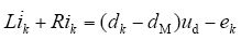
式中,k = a,b,c;ud为直流侧电压;ik为交流侧电流;L、R为交流侧串联电感、电阻;dk为逆变器第k相半桥上桥臂开关的占空比,dM为三相占空比的平均值,且dM = 0.5;设ek为三相等效电动势。
文献[6]采用常数变易法对上述模型的状态空间描述进行求解,得直流侧电流id和等效输入电导Gd
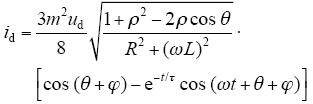
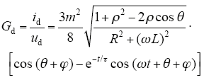
式中,m为逆变器PWM的调制系数;ρ为交流反电动势幅度因数,与负载交流大小有关,一般小于但近于1;τ为暂态分量的时间常数,τ = L/R。
鉴于上式所反映的直流侧伏安关系比较复杂,为简化分析,在等效电感L及时间常数很小的情况下,上述直流侧等效模型也可以用R-eL直流反电动势负载来近似等效模拟,如图2所示。
图2
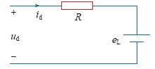
该电路满足
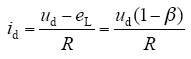
式中,β为直流反电动势幅度因数,β = eL/ud。
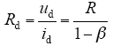
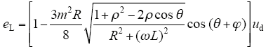
由式(2)~式(4)得等效输入电阻和直流反电动势
2.2 效率模型
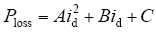
逆变器损耗可分为四类:电阻性损耗,即与电流平方成正比的损耗,例如线路和滤波电抗器内阻上的损耗、开关管通态损耗等;与电压电流之积成正比的损耗,例如开关管开关损耗;与电压平方成正比的损耗,例如均压电阻损耗、采样电阻损耗;固定损耗,例如控制系统功耗。
现代控制理论能够实现直流电压和电网电压的稳定,上述损耗可合并为三类:与电流平方成正比的损耗,与电流成正比的损耗和固定损耗。
图3
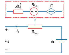
图3中,A、B、C分别为三类损耗的比例系数,进而得模型功率损耗
实际中对逆变器效率曲线的绘制是在标准测试条件下,测量5%、10%、15%、20%、25%、30%、50%、75%、100%负载点以及逆变器最大转换效率点和逆变器最大功率点的逆变效率。逆变器效率曲线测试,分别测量直流输入侧的瞬时功率值Pin,交流输出端的瞬时功率值Pout为
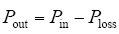
效率公式为
式中,a = A/ud,b = B/ud,c = C/ud。
参考SG 50k3型逆变器的实测曲线,如图4所示,采用待定系数法,运用cftool拟合得理论效率曲线。
图4
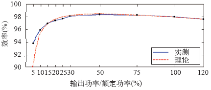
可见,采用本文方法计算的理论效率曲线与实测曲线整体趋势一致,且较为吻合。逆变器传输效率在高功率区间普遍较高,在低功率区间与传输功率成正比例关系,因此应尽量使逆变器工作在接近额定容量的高功率区间内(简称额定区间),以实现高效率运行,同时避免功率过高而导致安全问题。
3 逆变模块控制策略
3.1 多环控制策略
图5
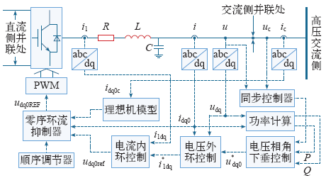
3.2 零序环流抑制策略
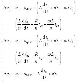
式中,udq0(LX)为实际运行状态下逆变器(理想机模型)输出电压;idq0(c)为逆变器输出(PCC处)电流。
为了增加控制器的快速响应能力和稳定性,增加PI控制环节
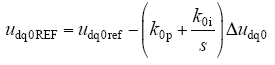
式中,udq0ref为经过电压电流双环控制后的参考电压;udq0REF为经过零序环流控制后的参考电压。
由式(10)和式(11)得控制框图如图6所示。
图6
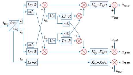
图6
零序环流抑制策略框图
Fig.6
Diagram of zero-sequence circulating current restraining strategy
4 投切控制策略
4.1 逆变器投切条件
规定每个逆变模块的额定区间为Prated,当前工作模块个数为n,根据逆变系统传输功率Psys的变化情况,总结系统状态见表1。
表1 系统状态
Tab.1
| 状态 | Psys | Psys变化程度 | Pin |
|---|---|---|---|
| 1 | 不变 | 恒定值 | =Pratedn |
| 2 | 不变 | 小范围波动 | =Pratedn |
| 3 | 增大 | 未引起逆变系统超载 | =Pratedn |
| 4 | 增大 | 导致逆变系统超载 | >Pratedn |
| 5 | 减小 | 未引起逆变系统轻载 | =Pratedn |
| 6 | 减小 | 导致逆变系统轻载 | <Pratedn |
4.2 逆变器投切控制策略
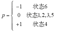
根据表1所示6种状态,将逆变器运行工况分为以下3类,作为逆变器投切依据。
(1)额定区间(状态1,2,3,5),逆变器工作于效率最佳的功率区间,增加并联数目会影响单个效率,并且增加系统整体成本,减少并联数目会导致设备超载,因而此时应尽量保持逆变模块数不变。
(2)超载功率区间(状态4),逆变器损耗以与电流成比例的损耗为主导,适当增加并联数目可以使单个逆变模块电流减小,保护电力电子设备,在不太影响单个模块效率的情况下,使得整体损耗减低,进而提高效率,因而此时应投入逆变模块。
(3)轻载功率区间(状态6),逆变器损耗以固定损耗为主导,并联数目增加会导致损耗等比增长,且使逆变器工作于更低功率区间,单个和整体效率都会降低,因而此时应切除逆变模块。
在选择逆变器投切次序时,为均衡器件工作时间,延长系统整体寿命,优先投入工作时间较短的模块,切除工作时间较长的模块。
4.3 基于模糊理论的投切控制
引入模糊理论,实现逆变器投切控制,控制框图如图7所示。
图7
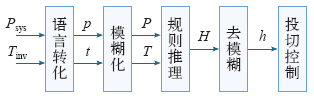
图中,Tinv为某个逆变模块累计工作时间;p、t为模糊控制器的两个输入量;h为输出量;P、T为两个输入语言变量;H为输出语言变量。
精确输入量通过下式转化为输入语言变量
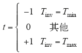
式中,Tmin、Tmax分别为所有逆变模块的最短和最长累计工作时间。
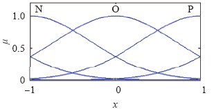
模糊控制器采用正态分布型隶属度函数
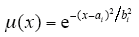
式中,x为语言变量;ai为函数的中心值;bi为函数的宽度。
本文共采用3个模糊子集{N、O、P },代表{负、零、正},如图8所示。
图8
输入量经隶属函数模糊化后按模糊规则继续处理,本文控制系统采用双输入单输出模式建立模糊规则,见表2。
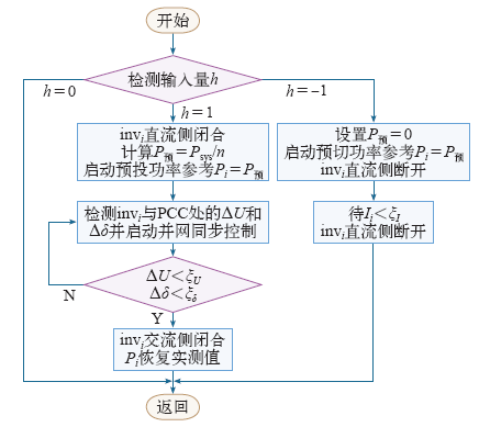
最后利用式(14)对经模糊规则处理的信号值做去模糊处理,得到输出h,作为逆变器投切控制的输入。本文采用交直流侧分步开合策略,抑制投切过程中的电流冲击,流程如图9所示。图中,invi为第i个逆变模块, 
图9
4.4 改进同步控制策略
逆变模块投入时,需要其输出电压幅值、频率和相位与PCC处一致。在不改变基本控制结构的基础上,将电压幅值差ΔU加入到幅值参考值中,实现电压幅值同步;利用锁相环技术提取待投入逆变器与PCC的相角差Δδ,反馈至相角参考值中,实现相位同步;由于采用相角下垂控制,待投入和已投入的逆变模块频率均为50Hz,因此投入前后频率信号始终同步。考虑到系统结构较小,各逆变模块物理距离很近,本文不考虑采样信号的延时问题。控制框图如图10所示。
图10
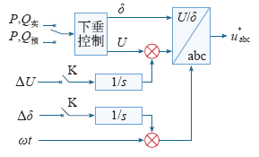
图中P,Q预是为实现逆变器平滑投切而加入的理论参考值,即在逆变模块投切完成前,先使其进入投切完成后的工作状态。投入并联运行后,相角与幅值差为零。切除逆变模块时,开关K首先开断,由于积分器作用,电压幅值与相位不会发生阶跃跳变,而是平缓地过渡到给定信号,因此大大减小了切除过程对系统的冲击。
5 仿真分析
5.1 仿真模型及参数
表3 设计参数
Tab.3
| 参 数 | 数 值 | |
|---|---|---|
| 高压直流 | Vdc/V | 18 000 |
| 滤波器 | R/Ω | 0.01 |
| L/mH | 22.27 | |
| C/μF | 31 | |
| 下垂系数 | m/(10-6rad/kW) | 6 |
| n/(10-2rad/kvar) | 6 | |
| 双环控制 | kip | [115,0.057 7] |
| kii | [205 944,333] | |
| 零序环流控制 | k0p | 10 |
| k0i | 1 000 | |
| 载波频率 | fz/Hz | 3 000 |
5.2 仿真工况模拟
仿真过程分为五个时间段,通过改变逆变系统的输入功率Pin,模拟逆变器投切的五种工况,参数变化见表4。
表4 仿真工况
Tab.4
| 工况 | |||||
|---|---|---|---|---|---|
| 1 | 2 | 3 | 4 | 5 | |
| 时间/s | 0~0.5 | 0.5~1.0 | 1.0~1.5 | 1.5~2.0 | 2.0~2.5 |
| Pin/kW | 500 | 700 | 600 | 200 | 1 000 |
5.3 仿真结果分析
图11
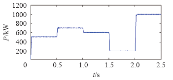
图12
图13
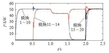
图14
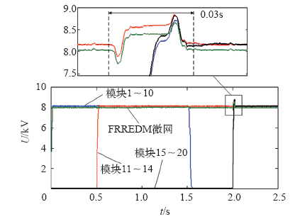
图14
逆变模块和FREEDM微网相电压幅值波形
Fig.14
Amplitude voltage wave of modular inverters and FREEDM
图15
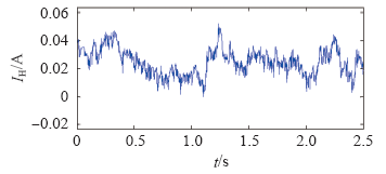
图15
零序环流绝对值平均波形
Fig.15
The average absolute value wave of zero sequence circulating current
当逆变系统传输功率按照图11所示波形变化时,各逆变模块的投切状态及功率变化如图13所示。0~0.5s时,1~10号模块投入使用,均处于额定区间,系统无投切动作;t = 0.5s时,系统功率突增至700kW,各逆变模块处于超载状态,11~14号模块逐步投入,使工作模块恢复至额定区间;t = 1.0s时,系统功率突降至600kW,各逆变模块仍处于额定区间,为避免逆变模块的频繁投切,延长开关装置寿命,系统无投切动作;t = 1.5s时,系统功率再降至200kW,各逆变模块处于轻载状态,为维持系统的高效率,同时考虑逆变系统的整体寿命,工作时间较久的1~10号模块逐步切除,使工作模块恢复至额定区间;t = 2.0s时,系统功率大幅突增至1MW,系统再次处于超载状态,1~10、15~20号模块迅速投入使用,使工作模块恢复至额定区间。
可见,在抑制策略的作用下,零序环流维持在很小的范围内,有利于提高系统整体运行效率。
6 结论
本文针对多逆变模块直接并联的分布式电源并网系统进行研究,根据单个模块工作效率与传输功率之间的规律,提出了适应分布式发电出力变化的直接并联逆变器投切控制策略,同时采用改进同步控制器和基于理想机模型的零序环流抑制策略,使逆变系统始终安全高效地运行。仿真结果表明,本文所提出控制策略,能够有效根据功率变化进行模块投切,并且保证较小的过电压和过电流对系统的冲击,对分布式电源并网发电具有参考意义。
参考文献
应用于智能微网的SVPWM固态变压器研究
[J].SST is the fundamental component of the innovative smart micro-grid future renewable electric energy delivery and managementl(FREEDM) proposed by NC State University. In this paper, the operating mode, system function and topology of SST are analyzed from the FREEDM's overall system objectives. A three phase SST model based on Chinese power system parameters is built. The control strategies of input AC-DC rectifier, DC-DC converter and output DC-AC inverter are illustrated respectively, and SVPWM control technique is adopted to strengthen SST's performance. Simulation results demonstrate that the SST can exchange energy with grid smoothly while operating under a unit power factor condition. The low voltage wave is a perfect sine curve. The SST has good stability when heavy disturbances occur. This paper will play a constructive role in promoting the FREEDM research in China.
Research on the SVPWM solid state transformer applied in smart micro-grid
[J].SST is the fundamental component of the innovative smart micro-grid future renewable electric energy delivery and managementl(FREEDM) proposed by NC State University. In this paper, the operating mode, system function and topology of SST are analyzed from the FREEDM's overall system objectives. A three phase SST model based on Chinese power system parameters is built. The control strategies of input AC-DC rectifier, DC-DC converter and output DC-AC inverter are illustrated respectively, and SVPWM control technique is adopted to strengthen SST's performance. Simulation results demonstrate that the SST can exchange energy with grid smoothly while operating under a unit power factor condition. The low voltage wave is a perfect sine curve. The SST has good stability when heavy disturbances occur. This paper will play a constructive role in promoting the FREEDM research in China.
软开关技术三相PWM逆变器及效率的分析研究
[J].
Analysis and study of soft-switched inverter and its efficiency
[J].
Coupled input-series and output-parallel dual interleaved flyback converter for high input voltage application
[J].DOI:10.1109/TPEL.2007.911867 URL [本文引用: 1]
共直流母线并联光伏逆变器的效率特性
[J].
Efficiency characteristic of parallel PV inverters with a common DC-bus
[J].
新能源并网三电平逆变器中低功率区间效率优化
[J].
DOI:10.7500/AEPS20130621006
URL
[本文引用: 1]

By virtue of its remarkably low voltage stress,low harmonics and low power loss,the three-level inverter is increasingly applied in renewable energy systems such as the solar and wind power system.Anyway,the manifest feature of the new energy generating system is power fluctuation.Proceeding from the stochastic power fluctuation,the conventional three-level inverter is evaluated in terms of its topological power loss first.Then,some new schemes of hardware and control strategies are proposed for a three-level inverter applied in a solar inverter.Finally,a prototype is built to verify the improvement.Test results show the proposed schemes can improve the efficiency of the three-level inverter,especially the efficiency in the low and medium power range.
Efficiency optimization in low and medium power range of new energy grid-connected three-level inverter
[J].
DOI:10.7500/AEPS20130621006
URL
[本文引用: 1]
By virtue of its remarkably low voltage stress,low harmonics and low power loss,the three-level inverter is increasingly applied in renewable energy systems such as the solar and wind power system.Anyway,the manifest feature of the new energy generating system is power fluctuation.Proceeding from the stochastic power fluctuation,the conventional three-level inverter is evaluated in terms of its topological power loss first.Then,some new schemes of hardware and control strategies are proposed for a three-level inverter applied in a solar inverter.Finally,a prototype is built to verify the improvement.Test results show the proposed schemes can improve the efficiency of the three-level inverter,especially the efficiency in the low and medium power range.
PWM逆变器的直流侧等效模型研究
[J].在三相并网型太阳能、风力发电系统和交-直-交变频调速传动系统当中,PWM逆变器作为直流侧的典型负载,其直流侧的静、动态行为,对于其前端变流器的建模、控制方法及静动态性能研究和系统设计都具有重要作用。该文通过研究逆变器与四象限变流器(4QC)拓扑结构的统一性,将4QC的状态空间平均(SSA)模型经过移植得到逆变器的SSA模型,进而提出逆变器直流侧的等效数学模型和近似简化等效模型;通过理论分析和仿真研究揭示PWM逆变器的直流侧等效模型与逆变器及交流侧电路参数之间的定量关系,并给出等效模型的参数设计公式。仿真与实验研究结果证明了所建模型及理论分析的正确性与可行性。
Research on the DC-side equivalent model of PWM inverters
[J].在三相并网型太阳能、风力发电系统和交-直-交变频调速传动系统当中,PWM逆变器作为直流侧的典型负载,其直流侧的静、动态行为,对于其前端变流器的建模、控制方法及静动态性能研究和系统设计都具有重要作用。该文通过研究逆变器与四象限变流器(4QC)拓扑结构的统一性,将4QC的状态空间平均(SSA)模型经过移植得到逆变器的SSA模型,进而提出逆变器直流侧的等效数学模型和近似简化等效模型;通过理论分析和仿真研究揭示PWM逆变器的直流侧等效模型与逆变器及交流侧电路参数之间的定量关系,并给出等效模型的参数设计公式。仿真与实验研究结果证明了所建模型及理论分析的正确性与可行性。
高压微网孤岛运行时频率稳定控制策略研究
[J].当采用大量电力电子设备的微网孤岛运行时,使用P/f下垂控制存在负荷快速分配与频率稳定控制之间的矛盾,为此,提出改进的P/?和Q/V下垂控制策略,将电压和相角偏差作为前馈量加入功率控制环节,实现电压和相角的二次调整,提高潮流变化时系统的动态适应性。仿真分析表明,所提出的控制策略不仅可实现负荷快速分配,而且相比P/f下垂控制具有更小的频率偏差,为高压微网孤岛运行时频率稳定控制提供了一种新方法。
Control strategies of frequency stability for islanding high-voltage microgirds
[J].当采用大量电力电子设备的微网孤岛运行时,使用P/f下垂控制存在负荷快速分配与频率稳定控制之间的矛盾,为此,提出改进的P/?和Q/V下垂控制策略,将电压和相角偏差作为前馈量加入功率控制环节,实现电压和相角的二次调整,提高潮流变化时系统的动态适应性。仿真分析表明,所提出的控制策略不仅可实现负荷快速分配,而且相比P/f下垂控制具有更小的频率偏差,为高压微网孤岛运行时频率稳定控制提供了一种新方法。
Control of circulating current in two parallel three-phase boost rectifiers
[J].DOI:10.1109/TPEL.63 URL [本文引用: 1]
The research on the zero sequence circulating current suppression in parallel inverters
[C].
逆变器并联系统中谐波环流抑制的研究
[J].
The research of harmonic circulating current restrain in parallel inverter systems
[J].
一种微电网多逆变器并联运行控制策略
[J].在微电网多逆变器并联系统中,由于逆变器的输出阻抗以及与公共连接点的线路阻抗存在差异,应用传统下垂控制法会导致逆变器间的环流较大及功率均分精度较低。在分析多逆变器并联系统中传统下垂控制法及逆变器输出阻抗对系统性能的影响基础上,通过引入感性虚拟阻抗,提出一种适合微网多逆变器并联的电压电流双环下垂控制策略。虚拟阻抗的引入使输出阻抗仅由滤波电感值决定,减少了逆变器输出电阻的影响;考虑线路阻抗的影响,提出一种新型改进下垂控制算法,通过对下垂系数进行修正,减弱了线路阻抗差异对并联均流的影响,提高了多逆变器并联性能。仿真与实验结果表明了该控制策略的正确性和有效性。
A control strategy for parallel operation of multi-inverters in microgrid
[J].在微电网多逆变器并联系统中,由于逆变器的输出阻抗以及与公共连接点的线路阻抗存在差异,应用传统下垂控制法会导致逆变器间的环流较大及功率均分精度较低。在分析多逆变器并联系统中传统下垂控制法及逆变器输出阻抗对系统性能的影响基础上,通过引入感性虚拟阻抗,提出一种适合微网多逆变器并联的电压电流双环下垂控制策略。虚拟阻抗的引入使输出阻抗仅由滤波电感值决定,减少了逆变器输出电阻的影响;考虑线路阻抗的影响,提出一种新型改进下垂控制算法,通过对下垂系数进行修正,减弱了线路阻抗差异对并联均流的影响,提高了多逆变器并联性能。仿真与实验结果表明了该控制策略的正确性和有效性。
模块化UPS采用虚拟阻抗的瞬时均流控制方法
[J].多逆变器并联系统中大多采用基于相量的均流控制策略,这种均流方式由于精度低,且缺乏对瞬时环流冲击的抑制能力,已逐渐被瞬时均流方式所取代。针对逆变器并联系统建立瞬时环流模型,提出一种在瞬时环流的反馈通路中引入虚拟阻抗的瞬时均流方法。通过合理配置该虚拟阻抗值可获得简洁的动态环流调节方程,从而实现良好的瞬时均流调节特性。分析表明,引入虚拟阻抗的瞬时均流方法具有很好的均流效果,且虚拟阻抗的引入并不影响并联系统的稳定性及输出特性。仿真与实验结果验证了所提出方法的优越性。
Instantaneous current-sharing control strategy for modular UPS using virtual impedance
[J].多逆变器并联系统中大多采用基于相量的均流控制策略,这种均流方式由于精度低,且缺乏对瞬时环流冲击的抑制能力,已逐渐被瞬时均流方式所取代。针对逆变器并联系统建立瞬时环流模型,提出一种在瞬时环流的反馈通路中引入虚拟阻抗的瞬时均流方法。通过合理配置该虚拟阻抗值可获得简洁的动态环流调节方程,从而实现良好的瞬时均流调节特性。分析表明,引入虚拟阻抗的瞬时均流方法具有很好的均流效果,且虚拟阻抗的引入并不影响并联系统的稳定性及输出特性。仿真与实验结果验证了所提出方法的优越性。
微网中分布式电源逆变器的多环反馈控制策略
[J].A multiple feedback loop control scheme for micro source inverters in Microgrid is developed in this paper. Based on the analysis of the inverter output impedance influenced by the line impedance parameters and the controller parameters, the voltage and the current controllers in the inner-loop are designed. The PI voltage regulator is applied to make the load voltage stable. The current loop uses the proportional regulator to improve the dynamic performance. After the output impedance is designed as an inductance impedance, the power controller in the outer-loop is produced based on the droop characteristics to achieve the wireless communication between paralleled inverters in Microgrid. With the implementation of the multiple feedback loop controller, the Microgrid can export high-quality power under the grid-connected mode. When the utility fault occurs, the Microgrid runs from grid-connected mode to islanding mode, and the designed controller will regulate the active and reactive power flow and enable power sharing between the paralleled micro sources in the Microgrid. Also, the controller can make the conversion between different modes seamless. The simulation results show the validity of the proposed scheme.
Multiple feedback loop control scheme for inverters of the micro source in microgrids
[J].A multiple feedback loop control scheme for micro source inverters in Microgrid is developed in this paper. Based on the analysis of the inverter output impedance influenced by the line impedance parameters and the controller parameters, the voltage and the current controllers in the inner-loop are designed. The PI voltage regulator is applied to make the load voltage stable. The current loop uses the proportional regulator to improve the dynamic performance. After the output impedance is designed as an inductance impedance, the power controller in the outer-loop is produced based on the droop characteristics to achieve the wireless communication between paralleled inverters in Microgrid. With the implementation of the multiple feedback loop controller, the Microgrid can export high-quality power under the grid-connected mode. When the utility fault occurs, the Microgrid runs from grid-connected mode to islanding mode, and the designed controller will regulate the active and reactive power flow and enable power sharing between the paralleled micro sources in the Microgrid. Also, the controller can make the conversion between different modes seamless. The simulation results show the validity of the proposed scheme.
下垂控制在基于固态变压器的高压微电网中的应用
[J].The application of droop control in microgrids is analyzed in theory. The rationality and superiority of the method used in high-voltage microgrids based on solid state transformer(SST) are given. The relationship between droop coefficient and system dynamic performance is studied, and the influence of droop coefficient on the stable range of frequency is analyzed. Droop control is achieved through high-voltage converter of SST, and the relationship between droop coefficient and capacity of SST is given as well. A circular high-voltage microgrid is established, the effect of proposed droop control method on stabilizing frequency and voltage in grid-connect mode, islanding mode and the switching period between two modes is simulated and analyzed. Results show that the voltage and frequency of microgid has good stabilizing performance in different modes.
Application of droop control in high-voltage microgrid based on solid state transformer
[J].The application of droop control in microgrids is analyzed in theory. The rationality and superiority of the method used in high-voltage microgrids based on solid state transformer(SST) are given. The relationship between droop coefficient and system dynamic performance is studied, and the influence of droop coefficient on the stable range of frequency is analyzed. Droop control is achieved through high-voltage converter of SST, and the relationship between droop coefficient and capacity of SST is given as well. A circular high-voltage microgrid is established, the effect of proposed droop control method on stabilizing frequency and voltage in grid-connect mode, islanding mode and the switching period between two modes is simulated and analyzed. Results show that the voltage and frequency of microgid has good stabilizing performance in different modes.
Renewable energy system research and education at the NSF FREEDM systems center
[C].
微网中下垂控制策略及参数选择研究
[J].To improve the applicability of conventional P-f and Q-V droop control methods of inverters in middle-voltage and low-voltage microgrids, this paper puts forward a novel control method of using virtual inductance and artificial output inductance in combination. A multiple feedback loop control strategy is proposed, the state-space equations are derived, and a complete small-signal model is established. Based on this, the matching principle of choosing virtual inductance and artificial output inductance is proposed. The inductance value is reduced significantly according to this principle, so problems of system stability and power loss are overcome. Simulation and analysis under linear and nonlinear load show that the proposed control strategy and parameter selecting method can not only enhance the output inductance of inverters, thus reduce the interference by line parameters, and also provide accurate load sharing, and inhibit circulating current effectively. This paper provides a new strategy for using conventional droop control in middle-voltage and low-voltage network.
Research on droop control strategy and parameters selection of microgrids
[J].To improve the applicability of conventional P-f and Q-V droop control methods of inverters in middle-voltage and low-voltage microgrids, this paper puts forward a novel control method of using virtual inductance and artificial output inductance in combination. A multiple feedback loop control strategy is proposed, the state-space equations are derived, and a complete small-signal model is established. Based on this, the matching principle of choosing virtual inductance and artificial output inductance is proposed. The inductance value is reduced significantly according to this principle, so problems of system stability and power loss are overcome. Simulation and analysis under linear and nonlinear load show that the proposed control strategy and parameter selecting method can not only enhance the output inductance of inverters, thus reduce the interference by line parameters, and also provide accurate load sharing, and inhibit circulating current effectively. This paper provides a new strategy for using conventional droop control in middle-voltage and low-voltage network.
The future renewable electric energy delivery and management(FREEDM) system: the energy internet
[J].
DOI:10.1109/JPROC.2010.2081330
URL
This paper presents an architecture for a future electric power distribution system that is suitable for plug-andplay of distributed renewable energy and distributed energy storage devices. Motivated by the success of the (information) Internet, the architecture described in this paper was proposed by the NSF FREEDM Systems Center, Raleigh, NC, as a roadmap for a future automated and flexible electric power distribution system. In the envisioned "Energy Internet," a system that enables flexible energy sharing is proposed for consumers in a residential distribution system. The key technologies required to achieve such a vision are presented in this paper as a result of the research partnership of the FREEDM Systems Center.
An empirical study of communication infrastructures towards the smart grid: design, implementation, and evaluation
[J].
DOI:10.1109/TSG.2012.2225453
URL
The smart grid features ubiquitous interconnections of power equipments to enable two-way flows of electricity and information for various intelligent power management applications, such as accurate relay protection and timely demand response. To fulfill such pervasive equipment interconnects, a full-fledged communication infrastructure is of great importance in the smart grid. There have been extensive works on disparate layouts of communication infrastructures in the smart grid by surveying feasible wired or wireless communication technologies, such as power line communications and cellular networks. Nevertheless, towards an operable, cost-efficient and backward-compatible communication solution, more comprehensive and practical understandings are still urgently needed regarding communication requirements, applicable protocols, and system performance. Through such comprehensive understandings, we are prone to answer a fundamental question, how to design, implement and integrate communication infrastructures with power systems. In this paper, we address this issue in a case study of a smart grid demonstration project, the Future Renewable Electric Energy Delivery and Management (FREEDM) systems. By investigating communication scenarios, we first clarify communication requirements implied in FREEDM use cases. Then, we adopt a predominant protocol framework, Distributed Network Protocol 3.0 over TCP/IP (DNP3 over TCP/IP), to practically establish connections between electric devices for data exchanges in a small-scale FREEDM system setting, Green Hub. Within the real-setting testbed, we measure the message delivery performance of the DNP3-based communication infrastructure. Our results reveal that diverse timing requirements of message deliveries are arguably primary concerns in a way that dominates viabilities of protocols or schemes in the communication infrastructure of the smart grid. Accordingly, although DNP3 over TCP/IP is widely considered as a smart grid communication solution, it cannot satisfy communication requirements in some time-critical scenarios, such as relay protections, which claim a further optimization on the protocol efficiency of DNP3.
高压微网运行模式切换控制策略
[J].
Control strategies of high-voltage microgrid for operation modes swiching
[J].
