


1 Introduction
Solar energy, as a kind of clean renewable energy, is developing rapidly. The proportion of large capacity photovoltaic grid renewable energy in the whole electrical power supply system is gaining a great increasing trend. Therefore, the effect of a photovoltaic power station running status on the stability when the grid fails must be taken into account[1,2]. Among them, the voltage drop will bring equipment a series of transient process. For this reason, referring to wind turbines interconnection regulation[3,4,5,6], grid of different nations proposed low voltage ride through requirements on their own condition[7,8]. In electricity supply and generation, low voltage ride through (LVRT) , is technology that an electric device, especially photovoltaic grid system, must be operated continuously without offline within certain range of voltage dip and timescale. To achieve LVRT, it must be ensured as premise that it can automatically detect the power grid voltage drop amplitude and phase fast and accurately[9,10]. Therefore, rapid and accurate automatic phase-locked control is the premise to achieve photovoltaic grid low voltage ride through.
Conventional three-phase PLL method is a method based on single synchronization coordinates system called SSRF SPLL, which only applies to three-phase balanced system. Article[11] uses a method based on double synchronization coordinates system named DDSRF SPLL, in order to measure plus and minus sequence simultaneously. Article[12] uses DSOGI-SPLL to avoid the complexity of double synchronization coordinates system. However, this method can’t endure with the influence of voltage offset, which usually is resulted from inaccuracy of measurement, data conversion and parameter estimation of grid voltage.
PLL being discussed in the articles above only detect phase voltage and are designed to modify the performance requirements of three-phase four-line grid connected system. Nowadays in photovoltaic grid connected system, three-phase grid connected inverter output is usually linked to grid by using Δ/Y transformer, which requires the output of grid connected inverter to be three-phase three-wire, i. e. three phase no-midline method. As neutral point drifting exists in three-phase three-wire system when grid voltage dips, the traditional phase-locked loop methods are unable to precisely measure the phase voltage. Therefore, it is imperative that precise PLL method for three-phase three-wire system is needed to be exploited to meet the demand of low voltage ride through in photovoltaic gird connected system.
In this paper, a new three phase imbalanced PLL method for three-phase three-wire system was proposed. This method primarily uses SOGI-PLL based on improved second order generalized integral so that the influence of voltage offset can be eliminated well, and simultaneously, precise phase lock and phase angle measurement are operated in line voltage of each phase. Then by calculating through phase voltage and line voltage, voltage amplitude and voltage phase of three phase which need to keep grid-connected are obtained. This method of phase-locked loop is able to detect voltage information and phase information in grid precisely and quickly, and it can be applied to low voltage ride through area in three-phase three-wire photovoltaic grid connected systems.
2 Design of Three Phase Imbalanced Phase Lock System
Three phase imbalanced PLL method applied to photovoltaic grid connected system low voltage ride through primarily consists of the following three parts:①measurement of line voltage amplitude and line voltage phase: using OSG-PLL to detect the phase angle, amplitude and frequency of the line voltage;②The choice of orthogonal signal generator (OSG) : using second order generalized Integrator (SOGI) as OSG;③transformation between line voltage and phase voltage: using Heron formula and sine theorem to transform triangle space between line voltage vector and phase voltage vector, then obtain amplitude and phase of three phase voltage which needs to keep grid-connected.
2.1 Measurement of Line Voltage Amplitude and Phase
Fig.1 shows the general structure of a single-phase PLL. Usually, the main difference among different single-phase PLL topologies is the orthogonal voltage system generation technique.
Fig.1
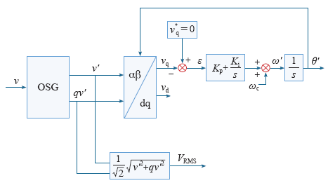
By using this phase-locked loop, we can measure each line voltage uab, ubc, uca and get three phase line voltage amplitude Uab, Ubc, Uca and the phase angle θab, θbc, θca.
2.2 The Choice of Orthogonal Signal Generator
This paper uses the proposed orthogonal signal generator (OSG) method relies on the second order generalized integrator (SOGI). The improved structure of SOGI-OSG is shown in Fig.2.
Fig.2
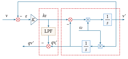
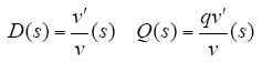
The transfer function is shown in Equ.(1) . D(s) and Q(s) respectively are closed-loop transfer functions corresponding to SOGI-QSG system; v is sine voltage signal input, v′ and qv′ have the same phase and amplitude; ω represents the resonance frequency of the SOGI and k respectively is the gain which affects the bandwidth of the OSG-SOGI structure. The Bode representations of D(s) and Q(s) , at different values of gain k, are showed in Fig.3.
Fig.3
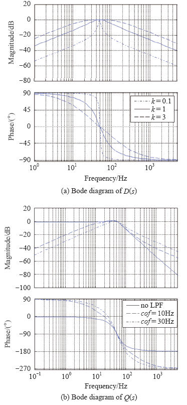
D(s) and Q(s) are secondary band pass filters. Judging from Fig.3, it can be seen that improved OSG-SOGI structure can eliminate the DC constituent of output signal v′ by negative feedback, meanwhile, and eliminate the DC constituent of output signal qv′ by adding a low pass filter.
2.3 Transformation of Line Voltage to Phase Voltage
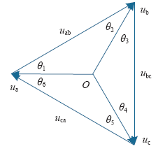
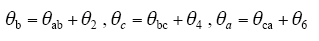
On the basis of three phase line voltage value and phase angle that we have gained above, by using calculating module we can achieving phase voltage of three phase ua, ub, uc. Their amplitude are Ua, Ub, Uc and their phases are θa, θb, θc. Voltage conversion control block structure presented in Fig.4. The relation of Line voltage and phase voltage is presented in Fig.5.
Fig.4
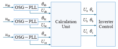
Fig.5
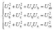
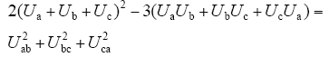
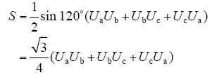
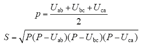
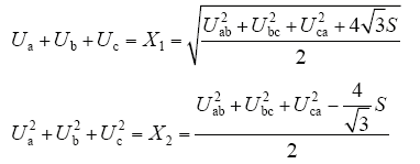
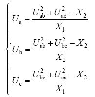
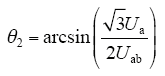
Solve the Equ.(2) , then add all the three equations of Equ.(2) , we will get Equ.(3) . By taking use of formula of Equ.(4) and Equ.(5) , triangle space formula and Heron formula, we get the functions of Equ.(6) and solution of Equ.(7) , then by using the cosine theorem we get Equ.(8) and Equ.(9) . Through the calculation above, we can get precise phase voltage value and phase angle value of three-phase three-wire grid connected system. Then Use inverse current control strategy to achieve grid connection.
3 Simulation and Analysis
To verify the validity of this method, this article utilizes the tool of SIMULINK to set up a three-phase three-wire grid connected system model, whose standard three phase voltage amplitude is 380V, grid frequency is 50Hz, filter coefficient k = 0.9, SRF-PLL PI controller parameter kp = 0.714, ki = 19.83.
3.1 Grid Voltage Offset
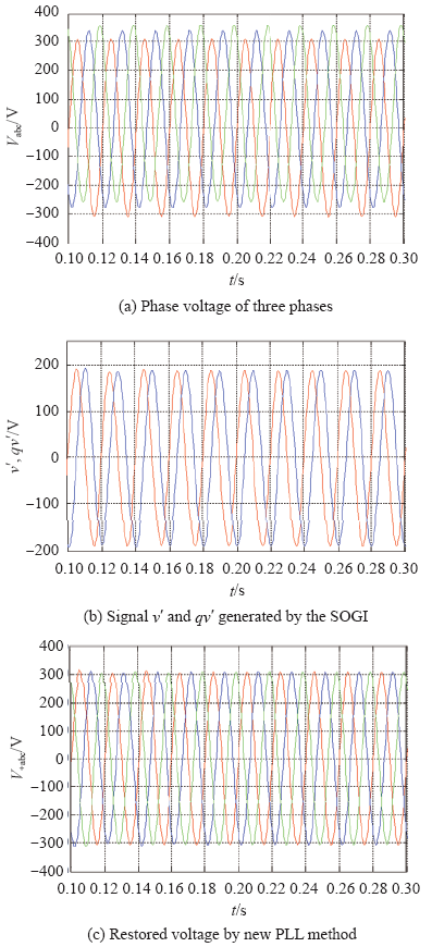
While system is in stationary state, the phase A keeps constant, the phase B has a voltage offset of 30V, and the phase C has voltage offset of 50V. Simulation result is shown in Fig.6. The result of simulation shows that the voltage offset is eliminated by this new PLL method.
Fig.6
3.2 Grid Voltage Dip
In order to simulate the voltage dip situation, when system is under stationary condition, voltage dip takes place at 0.3s and the voltage value of phase A drops to 0.8 of the original value and the ones of phase B and C drop to 0.2 of the original value. Result of the simulation is as Fig.7.
Fig.7
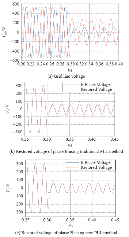
Fig.7 shows restored voltage of phase B using two different phase-locked loop method when grid voltage drops. The result of simulation indicates that in three-phase three-wire grid connected system, when voltage dip takes place, due to the offset of neutral point of three phase voltage, error exists in three-phase voltage of phase A, B, C that are sampled previously. Therefore, traditional three-phase imbalanced methods are unable to measure the amplitude and phase of the grid voltage precisely. By using new PLL method proposed in this article, we can measure and restore phase voltage of three-phase grid precisely. The effective voltage value of restored phase A is 175.51V, phase B and C are 43.88V. Compared with grid phase voltage that sags, the error is below 0.001%.
4 Experiments
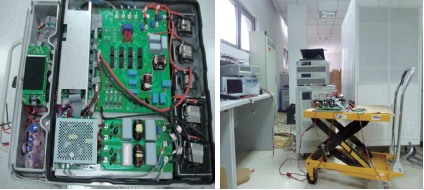
In order to validate and analyze the theory of PLL method presented in this paper, a three-phase 15kW PV inverter prototype has been developed shown in Figure 8. In the three-phase three-wire system, test results and analysis of the experimental are given.
Fig.8
4.1 Grid Connection Experiment
Fig.9 shows current and voltage waveforms of grid connection under normal voltage and phase conditions. From the result of the waveforms, it can be seen that the grid connection of the PLL method can accurately lock the phase, so the method can be applied into three-phase three-wire system.
Fig.9

4.2 Grid Voltage Jump Experiment
It is set in this experiment that PV energy is sufficient, and the prototype of the rated output 220V/50Hz. Some voltage jump tests are set as follows:
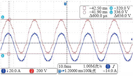
A transition of the output voltage which jumps 20V per-step: 180-200-220-240-260-240-220-200-180 in circulation is given to A phase, while output voltages of B phase and C phase are kept normal. The measured waveforms of A phase voltage and current are shown in Fig.10. A transition of the output voltage:190-240-270-220 is given to B phase, while output voltages of A phase and C phase are kept normal, the measured B phase voltage and current is shown in Fig.11.
Fig.10
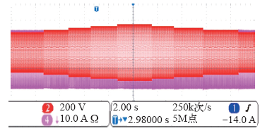
Fig.11
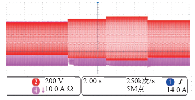
Experiment results show that when the voltage jump of the grid occurs, the prototype inverter can still ensure a normal output current, which verifies that the PLL method is available for timely and accurately grid voltage fault detection and completes the PLL process of three-phase three-wire system. So the method can be applied into the field of PV grid low voltage ride through controlling.
4.3 Harmonic Experiment
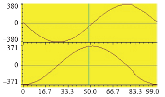
For the normal grid, rated output of voltage 220V/50Hz, set A phase injection of 1.5% 5th harmonic, 1.5% of 7th harmonic, 2% of the 19th harmonics; while B phase injection of 2% 3rd harmonic, 5% 5th harmonic, 5% 7th harmonic, 2% 15th harmonics; output waveforms are shown in figure 12 and figure 13, respectively. Experimental results show that the method can filter the grid voltage to lock the phase, and has the advantages of low output AC current harmonic and less electrical pollution into the grid.
Fig.12
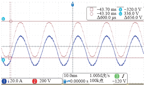
Fig.13
4.4 Voltage Drift Experiment
Because of the limit of the test system, result of this part can be only gotten from the internal DSP simulator. The waveform in figure 14 shows that there is a voltage drift of 50V DC of sampling voltage. After the process of the method, whose result is shown in figure 15 by 2 orthogonal signals, the voltage drift is eliminated.
Fig.14
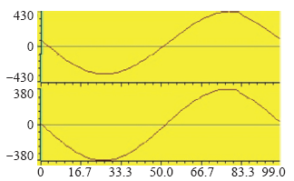
Fig.15
5 Conclusions
(1) In this paper, a new three-phase PLL approach was presented, in which improved second-order generalized integral orthogonal signal generator (SOGI-OSG) is used to detect of each phase of the line voltage. The simulation results show that the orthogonal signal generator can eliminate the offset voltage, filtering the detected grid voltage without delay accurately.
(2) According to the experiment results, the new PLL method proposed can be well adapted to the three-phase three-wire photovoltaic grid system, so it can avoid the shortcomings of the traditional locking method due to the neutral-point drift which can not accurately detect the phase voltage. So this proposed method can provide a good service for the study of low voltage ride through control in photovoltaic grid system.
参考文献
Overview of large-scale grid-connected photovoltaic power plants
[J].
Large-scale photovoltaic solar power integration in transmission and distribution networks
[C].
Dynamic characteristic analysis of doubly-fed induction generator low voltage ride-through based on crowbar protection
[J].
A low voltage ride-through control strategy of permanent magnet direct-driven wind turbine under grid faults
[J].
A low voltage ride-through control strategy of doubly fed induction generator
[J].
Based on an analysis of DFIG stator flux transient period during symmetric and asymmetric grid fault, its influence on DFIG rotor, the LVRT limiting condition using rotor-side converter (RSC) control strategy to achieve low voltage ride-through(LVRT) is found. A DFIG LVRT method combining the improved control strategy with hardware protect is studied when the limiting condition is not met. The method limits the stator’s and rotor’s over current, protects the rotor converter and provides power to the grid quickly during serious grid fault. A 3kW DFIG LVRT control experimental system is established. The experimental results prove that the LVRT control method of DFIG is effective.
Reactive current allocation and control strategies improvement of low voltage ride though for doubly fed induction wind turbine generation system
[J].
Low voltage ride-through modeling and control strategy for photovoltaic generation system based on RTDS
[J].Based on the real time digital simulator(RTDS), a low voltage ride-through(LVRT) real time digital simulation scheme is presented for the photovoltaic generation system. A set of LVRT simulation platform including the voltage sag generator, photovoltaic array, isolation transformer and photovoltaic grid-connected inverter, is built by RTDS big step models and small step models. A LVRT control strategy is designed to ensure the photovoltaic grid-connected inverter operate in three-phase grid voltages normal and symmetrical drop conditions. Finally, the LVRT simulation test and field experiment have been carried out for a 250 kW photovoltaic grid-connected inverter. The simulation and experiment results show that the RTDS simulation platform is able to simulate the on-site testing platform and the proposed control strategy has good dynamic as well as static characteristics in LVRT process.
Latest technical specifications and testing procedures for grid-connected photovoltaic power station in china
[C].
Enabling large-scale PV integration into the grid
[C].
Analysis of chinese photovoltaic generation system low voltage ride through characters
[C].
Dynamics assessment of advanced single-phase PLL structures
[J].
Advanced grid synchronization system for power converters under unbalanced and distorted operating conditions
[C].
