

1 引言
电机的通风结构以及冷却介质在电机内的分布特性均比较复杂,因此对电机内的流体特性进行有效分析,对电机冷却效果的提高以及更大容量电机的设计均具有重要应用价值。
本文以一台空–空冷中型异步电机为例,在流体力学理论、传热学理论和有限体积法的基础上对电机的流体场及温度场进行了计算。在基本假设的基础上,建立了电机三维流体与固体耦合直接求解电机温度场的求解模型。通过边界条件的施加,采用有限体积元法对其进行了数值求解,并将温度计算结果与实验结果进行对比分析,验证了求解方法及求解模型的正确性。
2 电机流体场的数学模型
电机冷却系统中流体流动的控制方程为:
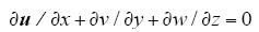
(1)质量守恒方程。电机内冷却流体为定常流动,且流体不可压缩,流体的密度ρ是常数,则可以得到三维、不可压缩流体稳态质量守恒方程
(2)动量守恒方程。电机内冷却流体的动量守恒方程为
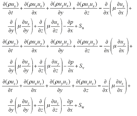
式中,p为流体微元体上的压力;ux、uy、uz为速度矢量u在x、y、z方向上的分量。
(3)湍流方程。标准k-ε两方程模型是在引入湍动能k的方程基础上,又引入了一个关于湍动耗散率ε的方程。这是目前应用最为广泛的湍流模型,也是在电机内冷却流体流动场合应用最多的模型。采用标准k-ε模型能够很好地模拟一般的湍流。
对于不可压缩流体,标准k-ε模型可以表示为
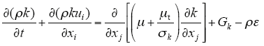
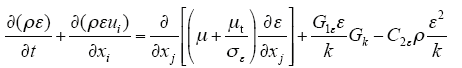
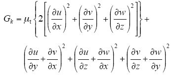
式中,μt为湍动粘度;i、j为下标,i, j=x, y, z且i≠j[10]。
3 电机温度场的数学模型
根据传热学的基本理论,在直角坐标系下,电机内的稳态温度场求解可归结为如下的边值问题
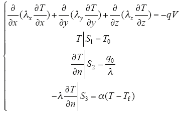
式中,λx、λy、λz分别为x、y、z方向上的导热系数;q为热源密度,是电机各部件单位体积产生的损耗;α为对流散热系数;Tf为周围流体的温度。
由变分原理可知,式(1)的等价变分方程为
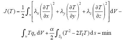
对其作离散化处理后,可得到三维温度场有限元方程

式中,T为求解域内全部节点温度所形成的温度阵列;K、F分别为总体系数矩阵和总体右端矢量。
对方程进行求解后可得到求解域内全部节点的温度值。
4 电机求解模型
4.1 电机基本数据及冷却系统结构
本文以一台空–空冷中型异步电机为例进行研究,电机的基本数据见表1。
表1 电机参数
Tab.1
| 参 数 | 数 值 | 参 数 | 数 值 |
|---|---|---|---|
| 额定功率/kW | 2 500 | 转子内径/mm | 350 |
| 额定转速/ (r/min) | 1 494 | 气隙长度/mm | 2.8 |
| 机座外径/mm | 1 280 | 额定电压/V | 6 000 |
| 定子外径/mm | 1 060 | 额定电流/A | 276 |
| 定子内径/mm | 700 | 效率(%) | 96.9 |
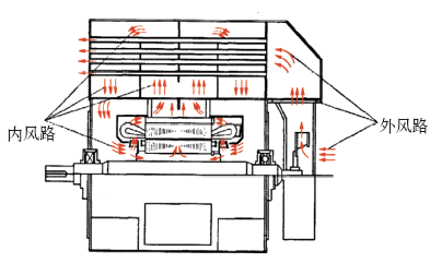
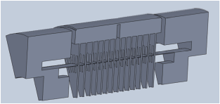
该电机采用空–空冷却系统,电机内部风路利用设置在转子两端的风叶将空气由两侧端盖抽入到机壳内,各自形成独立风路。每一条风路分为两条支路,一条支路通过转子风叶将空气送向绕组端部;另一条支路通过气隙将空气送入定子通风槽。两路气流汇合后经过电机上方的冷却器,将热量传递给外风路散发。
电机具体的冷却结构如图1所示。
图1
4.2 求解区域的确定
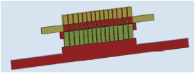
基于对称通风和周向对称原理,对电机内流体进行适当的简化计算,选取一个单元电机的大小,即转子对应4个槽,定子对应5个槽的宽度进行计算。流体场求解域如图2所示。
图2
为了计算方便,在温度场计算过程中,对电机进行如下假设:①认为定子槽内左、右侧绕组的发热情况相同,且忽略趋肤效应;②不对股线绝缘、层间绝缘以及主绝缘分别进行处理,而是将所有槽绝缘及槽内空气等效为一个绝缘实体,实体采用一个等效的导热系数;③假设电机浸漆状态良好、浸渍漆填充均匀、定子绕组铜线上的绝缘漆均匀分布、定子槽绝缘与定子铁心紧密接触无间隙及忽略股线间由于绝缘漆膜存在所造成的误差;④绕组端部伸出部分长度由等效的直线伸出长度来表示。
通过如上假设,可以将左、右侧绕组分别等效为一个整体的实心铜块;将浸渍漆、绕组的绝缘漆、槽绝缘和层间绝缘等效为一个统一的导热实体。
图3
5 边界条件
5.1 流体场的边界条件
流体场求解的边界条件为:环境温度为25℃,入口为空气入口,给定为速度入口边界,根据给定的质量流量数值,可求得入口速度,出口给定为压力边界。
电机入口风速如下

式中

式中,S为入口面积;P为电机损耗;CV为流体比热容;Δt为流体温度变化。
5.2 电机热源的分析
电机的热源主要来自各部分的损耗,各部分损耗见表2。
表2 电机各部分损耗(单位:kW)
Tab.2
| 损耗名称 | 损 耗 | 损耗名称 | 损 耗 |
|---|---|---|---|
| 定子轭部损耗 | 11.11 | 导条损耗 | 10.198 |
| 定子齿部损耗 | 8.73 | 机械损耗 | 19.89 |
| 定子铜耗 | 17.675 | 杂散损耗 | 12.50 |
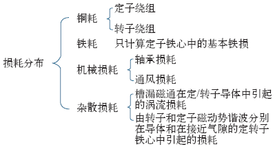
按照电机各部分所占体积的比例将铁耗、杂散损耗及机械损耗分离开来,分别施加到电机各部分上作为热源。具体损耗分布如图4所示。
图4
5.3 电机各部分的导热系数及边界条件
电机温度场计算的边界条件包括:生热边界、散热边界和绝热边界。发电机内发热体单位体积的生热量为生热边界;在模型的对称边界处为绝热边界,即不发生热交换;而散热边界则取决于电机的冷却条件,根据冷却介质的流速,计算电机内与冷却介质接触的不同部位的对流散热系数。不同的冷却系统结构,不同的冷却介质流速、不同的表面特性,对流散热系数均不相同。自然通风系统,机壳表面的对流散热系数与自然风吹拂的速度v之间的关系可以表示为[15]
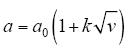
式中,α0为平静空气中的散热系数;k为吹拂效率系数,对于机壳表面,该数值取为1.3。
气隙的等效的导热系数可按如下方式进行计算:首先通过计算气隙中的雷诺数来判断气隙中空气流动的状态,气隙中的雷诺数

式中,ω为转子的圆周速度(即线速度);δ为气隙的长度;μ为空气的运动粘度。
与临界雷诺数进行比较,临界雷诺数
式中,R1为定子内径。计算得出Re>Reer,因此判断气隙中的空气流动为湍流,在这种状态下,气隙的有效导热系数
式中,η = r0/R1,r0为转子外径,R1为定子内径。计算出气隙的等效导热系数为0.319。
电机大部分材料的导热系数见表3。
表3 电机内材料的导热系数
Tab.3
| 部件名称 | 导热系数/(W/(m·K)) | ||
|---|---|---|---|
| x方向 | y方向 | z方向(轴向) | |
| 定子铁心 | 39 | 39 | 4.43 |
| 空气 | 0.030 5 | 0.030 5 | 0.030 5 |
| 定子绕组 | 385 | 385 | 385 |
| 槽楔 | 0.2 | 0.2 | 0.2 |
| 机壳 | 39.2 | 39.2 | 39.2 |
| 转子轭部 | 45 | 45 | 45 |
6 电机流体场与温度场计算结果分析
6.1 计算结果
中型异步电机内流体场计算结果如图5所示。
图5
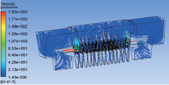
从总体流体迹线分布可以看出,由于气隙通道比较狭窄,当冷却空气进入到气隙通道时,截面积变小,由于挤压作用,在气隙通道的入口处,速度变高,这种趋势随着通道的深入而变缓,径向通风道起到了分流的作用,越靠近两端的通风槽,其槽内风速越高。各通风道内冷却气体流速见表4。
表4 电机各通风道内冷却气体流速
Tab.4
| 位置 | 风速/(m/s) |
|---|---|
| 通风道1 | 65.2 |
| 通风道2 | 18.0 |
| 通风道3 | 4.82 |
| 通风道4 | 1.33 |
| 通风道5 | 0.35 |
| 通风道6 | 0.09 |
| 通风道7 | 0.03 |
| 通风道8 | 0.04 |
| 通风道9 | 0.08 |
| 通风道10 | 0.32 |
| 通风道11 | 1.31 |
| 通风道12 | 4.8 |
| 通风道13 | 18.1 |
| 通风道14 | 65.0 |
电机温度场计算结果如图6所示。
图6
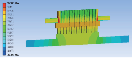
表5 电机温度场计算值
Tab.5
| 区域 | 温升/K |
|---|---|
| 最高温升 | 72.4 |
| 定子绕组最高温升 | 72.4 |
| 定子绕组平均温升 | 61.3 |
| 定子铁心平均温升 | 50.8 |
| 转子铁心平均温升 | 52.7 |
由计算结果可以看出,电机的最高温升出现在绕组端部,两端温度要比中间的温度低。
6.2 计算结果与实验数据对比
计算结果与实验数据对比见表6。
表6 电机温度场计算结果与实验数据对比
Tab.6
| 位置 | 温度场值/K | 误差值(%) | |
|---|---|---|---|
| 实验值 | 计算值 | ||
| 绕组端部 | 78.1 | 72.4 | 7.4 |
| 平均温升 | 73.6 | 68.9 | 6.4 |
由比较结果可以看出,温度场计算结果较为准确。
6.3 不同冷却风速下的分析
表7 不同冷却风速下气隙通道风速变化(单位:m/s)
Tab.7
| 冷却风速 | 气隙通道风速 |
|---|---|
| 3 | 41.55 |
| 3.5 | 47.97 |
| 4 | 53.58 |
| 4.5 | 64.23 |
| 5 | 66.47 |
| 5.5 | 72.39 |
| 6 | 78.19 |
图7
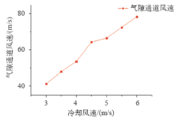
图7
气隙通道风速随冷却风速变化示意图
Fig.7
The curves of velocity rise in the channel gap of cooling wind velocity
可以看出,随着冷却风速的增大,气隙通道内冷却气体流速逐渐增大,且增大趋势非常明显。通风道内风速随冷却风速变化如图8所示。
图8
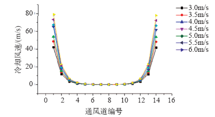
图8
通风道内风速随冷却风速变化示意图
Fig.8
The curves of velocity rise in the ventilation duct of cooling wind velocity
由图8可以看出,随着冷却风速的增大,靠近两端的通风道内冷却气体流速逐渐增大,而靠近中间的通风道内冷却气体流速变化不大。冷却风速的改变对靠近两端的通风道产生的影响比靠近中间的通风道要严重。
7 结论
本文通过对空-空冷中型异步电机流体场及温度场进行计算分析,得出如下结论:
(1)通过流体场的计算分析,得到了冷却通道内流体流速的分布。
(2)通过三维温度场的计算可以得出电机温度的分布规律,电机的整体温度分布沿径向中心线大致呈两端对称趋势,电机的最高温升出现在定子下层绕组的端部靠近定子铁心的部分。
(3)电机的温升计算结果与实验结果吻合,本论文所确立的求解域合理,本文采用的计算方法正确。
(4)随着冷却风速的增大,气隙通道内冷却气体流速逐渐增大,且增大趋势非常明显;靠近两端的通风道受到的影响比靠近中间的通风道要大。
参考文献
高能量密度水冷电机冷却系统设计与热力计算
[J].
Design of cooling system and calculation of heating on water-cooled motor with high-energy density
[J].
Thermal analysis of a permanent magnet synchronous motor for electric vehicles
[J].
大型空冷汽轮发电机定子端部温度场与流体场的计算与分析
[J].
根据200 MW大型空冷汽轮发电机通风系统内流体流动与传热的特点,建立定子端部和多风路通风系统三维流动与传热耦合计算的数学模型和物理模型,并给出求解域相应的边界条件及假设条件,采用有限体积法对流体场和温度场控制方程进行耦合计算,可以得到定子端部流体出口处流量及端部绕组、压板周围的流体速度空间分布特性,从而确定多风路求解域中各风路入口的边界条件及端部各结构件的散热系数。分析了端部绕组、压板周围不同散热系数下,定子绕组、铁心、压指和压板温度的分布情况。将耦合场计算结果与实测结果进行分析,结果表明,端部计算模型计算出的各风路风量可作为多风路模型计算中各入口的流量边界条件,也表明多风路模型中的基本假设是合理的。结论对大型电机定子端部散热系数选择提供方法和依据。
Temperature and fluid flow field calculation and analysis of stator end of air cooled turbo-generator
[J].根据200 MW大型空冷汽轮发电机通风系统内流体流动与传热的特点,建立定子端部和多风路通风系统三维流动与传热耦合计算的数学模型和物理模型,并给出求解域相应的边界条件及假设条件,采用有限体积法对流体场和温度场控制方程进行耦合计算,可以得到定子端部流体出口处流量及端部绕组、压板周围的流体速度空间分布特性,从而确定多风路求解域中各风路入口的边界条件及端部各结构件的散热系数。分析了端部绕组、压板周围不同散热系数下,定子绕组、铁心、压指和压板温度的分布情况。将耦合场计算结果与实测结果进行分析,结果表明,端部计算模型计算出的各风路风量可作为多风路模型计算中各入口的流量边界条件,也表明多风路模型中的基本假设是合理的。结论对大型电机定子端部散热系数选择提供方法和依据。
基于流体传热理论永磁风力发电机组温度场计算
[J].
Calculation of tempera-ture field of PM generator for wind turbine based on theory of fluid heat transfer
[J].
高速永磁电机的损耗计算与温度场分析
[J].Due to the high speed and high frequency of the winding current for the high speed machines, the core and copper losses of stator, eddy current loss and air friction loss of the rotor per unit volume will be much more compared to the normal speed machine. At the same time, because of the power density increasing and the total dissipation area decreasing, the effective dissipation and cooling mode are significant to the high speed machine design. In this paper, the basic electrical loss, the high frequency additional loss and the air friction loss on the rotor surface are analyzed based on the finite element and 3D fluid field analysis. Taking a high speed permanent magnet (PM) machine with rated speed of 60000r/min as an example, the calculation and experimental methods of losses are studied. The temperature field of the high speed PM machine is calculated by using the fluid-solid coupling method. The validity of the temperature field calculation method is confirmed through the comparison of the calculated value with the tested result of the high speed PM machine.
Losses calculation and temperature field analysis of high speed permanent magnet machines
[J].Due to the high speed and high frequency of the winding current for the high speed machines, the core and copper losses of stator, eddy current loss and air friction loss of the rotor per unit volume will be much more compared to the normal speed machine. At the same time, because of the power density increasing and the total dissipation area decreasing, the effective dissipation and cooling mode are significant to the high speed machine design. In this paper, the basic electrical loss, the high frequency additional loss and the air friction loss on the rotor surface are analyzed based on the finite element and 3D fluid field analysis. Taking a high speed permanent magnet (PM) machine with rated speed of 60000r/min as an example, the calculation and experimental methods of losses are studied. The temperature field of the high speed PM machine is calculated by using the fluid-solid coupling method. The validity of the temperature field calculation method is confirmed through the comparison of the calculated value with the tested result of the high speed PM machine.
某新型通风方式空冷汽轮发电机转子三维温度场
[J].In order to analyze the temperature distribution of an air-cooled turbo-generator with a new type ventilation system, a model for the NO.8 slot of half axis length is established. The 3D temperature field is calculated by using the finite volume method (FVM) based on the principle of computational fluid dynamics(CFD). Then the temperature distribution of cooling air, winding, insulating material, wedges and cord is obtained, as well as the surface heat transfer coefficient of radial air duct. The results show that, in this type of ventilation, the winding temperature gradually is increased along the axial direction; the rotor end is a low temperature part; the peak temperature of winding is located at the centrosymmetric face. The conclusion will provide theoretical references for thermal design of rotor of large turbo generator.
Temperature field of one air-cooled turbo-generator rotor with new ventilation type
[J].In order to analyze the temperature distribution of an air-cooled turbo-generator with a new type ventilation system, a model for the NO.8 slot of half axis length is established. The 3D temperature field is calculated by using the finite volume method (FVM) based on the principle of computational fluid dynamics(CFD). Then the temperature distribution of cooling air, winding, insulating material, wedges and cord is obtained, as well as the surface heat transfer coefficient of radial air duct. The results show that, in this type of ventilation, the winding temperature gradually is increased along the axial direction; the rotor end is a low temperature part; the peak temperature of winding is located at the centrosymmetric face. The conclusion will provide theoretical references for thermal design of rotor of large turbo generator.
旋转电磁致热器热网络模型及其温升计算
[J].
Lumped parameter thermal model and computation of temperature rise of rotational electromagnetic heater
[J].
永磁风力发电机流场与温度场耦合分析
[J].In order to estimate operating stability of wind generator stator winding and permanent magnet in operation, it is necessary to calculate the thermal field of gengertor. A 100kW, 100r/min radial flux permanent magnet synchronous wind generator was investigated, firstly using finite element method to calculate the temperature field. Some key factors that may have a great influence on thermal analysis are considered. At last, the comparisons of the analysis results with test data were proposed to verify the correctness of calculation. Conclusions can be drawn to provide certain references for designing the permanent magnet synchronous wind generator.
Investigation of fluid field and thermal field coupled for permanent magnet wind generator
[J].In order to estimate operating stability of wind generator stator winding and permanent magnet in operation, it is necessary to calculate the thermal field of gengertor. A 100kW, 100r/min radial flux permanent magnet synchronous wind generator was investigated, firstly using finite element method to calculate the temperature field. Some key factors that may have a great influence on thermal analysis are considered. At last, the comparisons of the analysis results with test data were proposed to verify the correctness of calculation. Conclusions can be drawn to provide certain references for designing the permanent magnet synchronous wind generator.
永磁风力发电机三维温度场计算及分析
[J].In order to estimate operating stability of wind generator stator winding and permanent magnet in operation, it is necessary to calculate the thermal field of gengertor. A 100kW, 100r/min radial flux permanent magnet synchronous wind generator was investigated, firstly using finite element method to calculate the temperature field. Some key factors that may have a great influence on thermal analysis are considered. At last, the comparisons of the analysis results with test data were proposed to verify the correctness of calculation. Conclusions can be drawn to provide certain references for designing the permanent magnet synchronous wind generator.
Thermal analysis and calculation of permanent magnet wind generators
[J].In order to estimate operating stability of wind generator stator winding and permanent magnet in operation, it is necessary to calculate the thermal field of gengertor. A 100kW, 100r/min radial flux permanent magnet synchronous wind generator was investigated, firstly using finite element method to calculate the temperature field. Some key factors that may have a great influence on thermal analysis are considered. At last, the comparisons of the analysis results with test data were proposed to verify the correctness of calculation. Conclusions can be drawn to provide certain references for designing the permanent magnet synchronous wind generator.
典型空-空冷电机通风冷却系统研究
[J].
Analysis and development on ventilation system of AC/DC motors
[J].
大型水轮发电机转子旋转状态下磁极间流体流动与温度场分析
[J].以1台250 MW大型水轮发电机为例,建立了流体与固体耦合传热三维模型,采用共轭传热法对转子半个轴向段的流体场与温度场进行了计算。分析了磁极间隙内流体流动形态对励磁绕组冷却效果的影响和不同入口流量下磁极间涡流变化规律。为减小涡流对转子散热的抑制作用,在转子磁极间增加一轴径向挡风结构,并通过数值模拟分析了挡风结构对涡流的减弱作用以及对励磁绕组冷却效果的影响。
Fluid flow and temperature field analysis between two poles of a large air-cooled hydro-generator rotor in rotation
[J].以1台250 MW大型水轮发电机为例,建立了流体与固体耦合传热三维模型,采用共轭传热法对转子半个轴向段的流体场与温度场进行了计算。分析了磁极间隙内流体流动形态对励磁绕组冷却效果的影响和不同入口流量下磁极间涡流变化规律。为减小涡流对转子散热的抑制作用,在转子磁极间增加一轴径向挡风结构,并通过数值模拟分析了挡风结构对涡流的减弱作用以及对励磁绕组冷却效果的影响。
Design and optimization of a nine-phase axial-flux PM synchronous generator with concentrated winding for direct-drive wind turbine
[J].DOI:10.1109/TIA.2008.921379 URL [本文引用: 1]
