


1 Introduction
The calculation of losses in electrical machines has attracted a great deal of attention in recent years since reducing losses may facilitate energy saving and environmental pollution reduction. However, an accurate calculation of rotor eddy current losses is still a challenge especially for special induction motors [1].
Several papers have been dealing with the calculation of rotor eddy current losses of rotating machines. It is confirmed that the rotor surface losses (eddy current losses on the rotor surface) are caused by the slotting effect and the harmonic currents [2,3]. The rotor eddy current losses in permanent magnet motors were widely studied and they can be obtained by analytical method, finite element method or experiment method [4,5]. Y.Amara et al. presented an analytical method for calculating the eddy current losses in the moving armature of a tubular permanent magnet machine [6]. Dahaman et al. developed an analytical model for predicting the eddy current losseses in the rotor magnets of permanent magnet brushless machines which have a fractional number of slots per pole [7]. It can account for space-harmonic magnetomotive forces (MMF) resulting from the winding distribution and time-harmonic MMF due to non-sinusoidal phase currents. Jiabin Wang et al. proposed an analytical formula for predicting eddy current losses in each segment of permanent magnet brushless machines and concluded that forward and backward rotating space harmonics of different orders may result in the same frequency seen by the rotor [8]. However, the presented analytical techniques are not suitable for predicting the eddy-current losses in individual segments when more than two segments per pole are employed. In the case of permanent magnet synchronous motors, two-dimensional analytical method was first proposed by Frederic Dubas and the effects of the rotor speed and the initial rotor mechanical angular position were also investigated [9]. The analytical method can give a good prediction for evaluation rotor eddy current losses, but the accuracy is limited since many assumptions are made. Finite element methods including post1-D, 2-D and 3-D were widely employed in many papers for calculating the rotor eddy current losses [10,11,12,13,14]. Apart from calculating the rotor eddy current losses, many papers focused on reduction of rotor eddy current losseses in permanent magnet motors [15,16,17,18]. Shuangxia Niu et al. proposed a method called axial segmentation of the permanent magnets to cut off the eddy-current axial paths [15]. In the paper, the steady-state and dynamic characteristics of the permanent magnet motors were performed by a nodal method based on network-field coupled multislice time stepping finite element method. Jianxin Shen et al. presented grooving retaining sleeve method for reduction of rotor eddy current losses in high speed permanent magnet machines and concluded that the circumferential grooving is the most effective one to reduce the rotor eddy current losses [16]. In addition, the optimized design of rotor shape is an effective method for reducing rotor surface loss in the case of interior permanent magnet synchronous motor [17,18].
Although many papers investigated the rotor eddy current losses of the permanent magnet motors, few concentrated on the induction machines. High-frequency loss calculation in smooth rotor induction motor was presented in Ref.[19], and the approach was useful for the prediction of high-frequency losses at the design stage. Omar Laldin et al. employed the circuit models for predicting the core losses in a caged induction machine but the mechanism of rotor eddy current losses was not presented [20]. In Ref.[21] 3-D finite element analysis of additional eddy current losses in induction motors was performed but the aim was to extend the loss computation to the end-ring of the squirrel cage induction machine. In Ref.[22] stray load losses in cores and secondary conductors of induction motor without skew was evaluated by 2-D finite element method. However, the causes of the stray load losses were not investigated and the reduction was not made. Paul Handgruber et al. studied the effects of skewing on the loss behavior of a slip-ring induction machine [23]. However, the paper concentrated on the stator sheet model and gave no presentations about rotor eddy current losses.
It is confirmed that the air gap permeance harmonics produced by stator slotting can cause rotor surface losses. However, the permeance harmonics are rather difficult to calculate because of saturation and non-linear of the material. Because of this problem, Steve et al. proposed an analytical method for determining the slot-harmonic fields in the air gap which are produced by the currents flowing in closed rotor slots [24]. However, the stator slotting effects were not considered. As mentioned before, no one puts forward a model of electrical submersible motor with different stator slot types for the calculation of rotor surface losses at no-load condition.
In this paper, the Carter Factor of the submersible motor with different stator slot types is calculated. Since the stator tooth harmonic fields caused by stator slotting are the primary cause of the rotor surface loss at no-load condition, the harmonic air-gap permeance distributions produced by stator slotting were analyzed and the tooth harmonic fields caused by stator slotting were presented by analytical expressions. Then the rotor surface losses were calculated and the penetration depth was considered. Moreover, the flux density of the tooth harmonic caused by the stator slotting was separated from the total tooth harmonic. Finally, the rotor surface losses of the submersible with open stator slots and closed stator slots were analyzed and an improved stator slot was proposed for reduction of rotor surface losses in submersible motor.
2 Analytical Model of Closed-Slot Machine
Fig.1
3 Rotor Surface Losses in Closed-Slot Submersible Motor
3.1 Carter Factor
The Carter Factor for stator slotting can be expressed as
where ts is the stator slot pitch; b0 is the stator slot opening.
When both the stator and the rotor surface are split with slots, we first calculate Kcs by assuming the rotor surface to be smooth. Then calculations are repeated by assuming the stator surface to be smooth and the total Carter Factor can be written as [25]
In this paper, four stator slot types including full-open slot, semi-open slot, original slot and improved slot are introduced, as shown in Fig.2. According to the analytical method, the Carter Factors of the models with the full-open slot and the semi-open slot are 1.45 and 1.14, respectively. Both Carter Factors of the models with closed slot types are zero. The calculation results of the Carter Factor varied with the stator slot opening are shown in Fig.3.
Fig.2
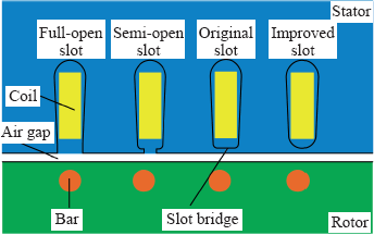
Fig.3
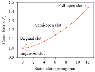
Fig.3
Calculation results of the Carter Factor varied with the stator slot opening
3.2 Analysis of Magnetic Field
The rotor surface experiences alternating flux components because of a changing permeance caused by the slots. The harmonic air-gap permeance distribution produced by stator slotting has the general forms.
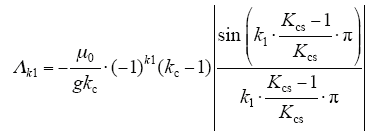
where g is the air gap length; Kcs is the Carter factor for the stator slotting; Kc is the Carter factor for both the stator slotting and rotor slotting; μ0 is the vacuum permeability; 
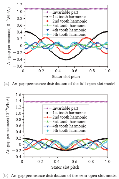
The harmonic air-gap permeance distributions of full-open slot model and semi-open slot model are shown in Fig.4. It can be seen from Fig.4 that the invariable part of the air gap permeance of the full-open slot model is smaller than that of the semi-open slot model. However, the first order harmonic air gap permeance of the full-open slot model is much larger than that of the semi-open slot model. In the case of the full-open slot model, the air gap permeance from big to small are 1st, 2nd, 5th, 4th and 3rd, respectively. However, in the case of the semi-open slot, the air gap permeance from big to small are 1st, 2nd, 3rd, 4th and 5th, respectively. This is because the amplitude of the air gap permeance caused by slotting effect is affected by the Carter Factor and the harmonic order.
Fig.4
Then the tooth harmonic fields caused by stator slotting can be expressed as
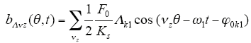
where F0 is the amplitude of synthetic magnetic potential; Ks is saturation coefficient; φ0k1 is the initial phase angle; νz = ±k1Z1 + p, k1 = 1, 2, ….
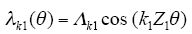
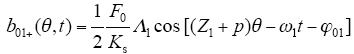
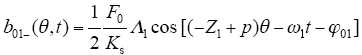
It should be noted that the first order forward-rotating and backward-rotating magnetic fields produced by stator slotting can be written as
The results of the first order magnetic field (including the forward-rotating magnetic field and the backward-rotating magnetic field) and the total magnetic fields caused by stator slotting are shown in Fig.5. It can be concluded that the distribution of the first order magnetic field of the full-open slot model has a similar trend with that of the semi-open slot model. However, the amplitude of the first order magnetic fields of the full-open slot is much larger than that of the semi-open slot. In addition, the amplitude of the total magnetic field of the full-open slot model is approximately equal to that of the semi-open slot. The amplitudes of the harmonic fields of the full-open slot model and the semi-open slot model are concluded as shown in Tab.1.
Fig.5
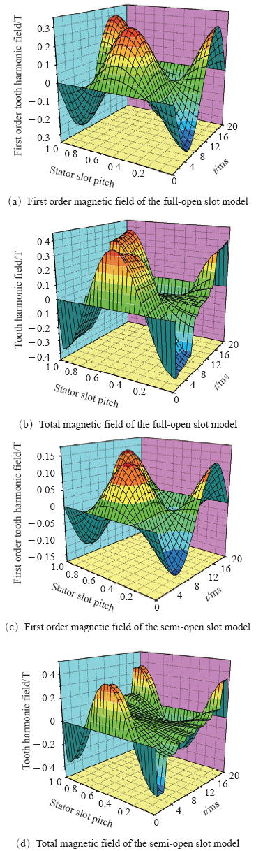
Fig.5
Results of the first order magnetic field and the total magnetic field caused by stator slotting
Tab.1 Amplitudes of the harmonic fields
| Harmonic order | Amplitude of forward-rotating tooth harmonic field/T | |
|---|---|---|
| Full-open slot | Semi-open slot | |
| 1st order | 0.151 | 0.070 |
| 2nd order | 0.085 | 0.060 |
| 3rd order | 0.014 | 0.056 |
| 4th order | 0.031 | 0.046 |
| 5th order | 0.035 | 0.034 |
| Total | 0.188 | 0.186 |
3.3 Analytical Calculation of Rotor Surface Losses
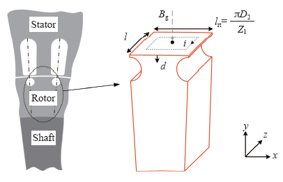
Although the magnetic cores are made of sheets, a thin sheet also enables eddy currents to occur when the flux alternates. According to Lenz’s law, the eddy currents try to prohibit the flux from penetrating the laminations, as shown in Fig.6. In the figure, d is the penetration depth of the eddy current induced in rotor, l is the thickness of the lamination, and lrt is the average eddy current path width. More details of eddy current path can be found in Ref.[19].
Fig.6
The governing equations in rotor can be written as
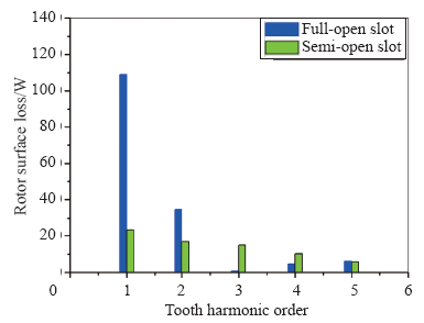
where ωz is the angular frequency of eddy current; ρ is the resistivity of the rotor; μ is the permeability of the rotor; j is the imaginary unit; Jz is the eddy current density.
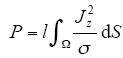
By assuming the distribution of the tooth harmonic is sinusoidal, we can obtain the rotor surface loss density caused by the air gap permeance harmonic magnetic field as following formula
where Z1 is the number of stator slots; t1 is the stator tooth pitch; n is the rotating speed which is approximately equal to synchronous speed at no-load condition; k0 is a coefficient which is related to the resistivity and the permeability of the rotor; B0 is the amplitude of the tooth harmonic flux density caused by the stator slotting.
Then the total rotor surface loss can be written as
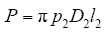
Fig.7 shows the analytical calculation results of the rotor surface losses. It is concluded that the first order of the tooth harmonic can produce the largest rotor surface loss in case of both the full-open slot model and the semi-open slot model. It should be noted that the third order tooth harmonic of the full-open slot model is much smaller than others since the tooth harmonic field is the smallest among the five orders in case of the full-open slot model.
Fig.7
3.4 Finite Element Analysis of Rotor Surface Losses
3.4.1 Finite Element Model
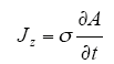
In this paper, models with four different stator slot types are solved by 2-D transient magnetic field analysis as space-harmonic magnetic problems. Maxwell’s equations for each region can be written as [3]
Where 


For all practical purposes, it is sufficient for us to consider a 2-D model by assuming symmetry along the axial direction. Then the eddy currents would appear to be flowing in the axial direction [19]. Eddy current density induced from the time-varying magnetic field in case of 2D problem can be expressed as
Then the rotor surface loss can be written as
where l is the depth of model; S is the area of the rotor region considering the penetration depth of the eddy current.
The penetration depth of the eddy current induced in rotor can be expressed as [14]
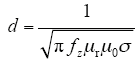
where d is the penetration depth of the eddy current; fz is the frequency of the eddy current; μr is the relative magnetic permeability of rotor; μ0 is the vacuum permeability; σ is the electrical conductivity of rotor.
Hence, the rotor surface loss is
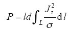
where l is approximately equal to the outer perimeter of the rotor.
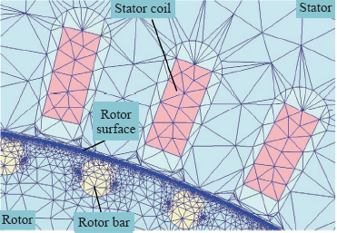
The penetration depth of the eddy current is calculated to be 0.2mm. This means that the mesh of the rotor surface is of great significance due to the skin depth. In order to improve the calculation accuracy, the maximum normal deviation is set to be 1deg. The skin depth is set to be 0.2mm, and the number of layers of elements is set to be 5. The finite element model and meshes are shown in Fig.8.
Fig.8
3.4.2 Analysis of Magnetic Field
In this section, the magnetic field is analyzed, as shown in Fig.9, and the mechanism of the rotor surface loss is investigated by using the spatial distributions of the flux densities in the air gap, as shown in Fig.10. The Fast Fourier Transformation (FFT) of the air gap flux densities of the four slot types are shown in Fig.11. It can be seen from Fig.10 and Fig.11 that the flux density of the full-open slot has serious wave distortion, and the flux density of the improved slot is in good agreement with sinusoidal wave. This is because the stator slotting has a significant influence on the air gap permeance which affects the flux density distribution.
Fig.9
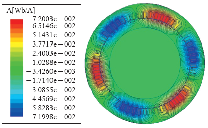
Fig.10
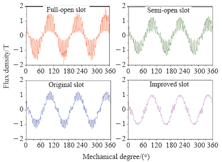
Fig.11
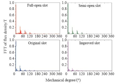
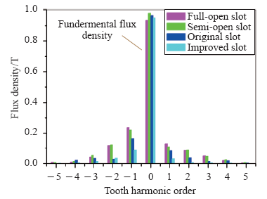
The amplitude of the tooth harmonic flux density can be obtained by FFT analysis of radial air gap flux density, as shown in Fig.12. It can be seen from Fig.12 that spatial harmonics of the open slot models including full-open slot model and semi-open slot model are larger than the spatial harmonics of the closed slot models (including the original slot and the improved slot models). In addition, the amplitudes of the tooth harmonics are much larger than the others.
Fig.12
It should be noted that the stator tooth harmonics caused by stator slotting and the stator harmonics caused by stator MMF have the same frequencies and the same pole numbers. This means that results obtained by the FFT analysis of air gap flux densities, as shown in Fig.11and Fig.12, include both the stator tooth harmonics caused by stator slotting and the stator harmonics caused by stator MMF. However, at the no-load condition, the rotor speed is very close to the synchronous speed. Hence, the stator tooth harmonic field caused by stator slotting is the primary cause of the rotor surface loss at no-load condition.
The stator tooth harmonic field caused by stator slotting can be separated from the total stator tooth harmonics as shown in Fig.13. The angle between the stator tooth harmonics 

Fig.13
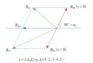
Fig.13
Sketch of separating stator tooth harmonic field caused by stator slotting from the total stator tooth harmonics
Fig.14
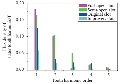
It can be seen from Fig.14 that the flux density of the stator tooth harmonic caused by stator slotting is affected by the slot opening as well as the slot type. In general, the stator tooth harmonics of the motor with large slot opening are larger than those of the motor with small slot opening. But this is not always true because the flux density of the stator tooth harmonic is affected by the harmonic air gap permeance distribution which depends on the Carter Factor and the tooth harmonic number. Moreover, the flux density of the stator tooth harmonic caused by stator slotting is not zero and the amplitude is influenced by the slot shape. According to the previous analytical method of calculating Carter Factor, the Carter Factor of the closed-stator-slot motor is equal to 1. However, the authors believe that the Carter Factor of the closed-stator-slot motor is not equal to 1 because the flux density in the slot bridge is highly saturated due to the narrow and long shape. This gives a good explanation that the stator tooth harmonic of the closed-stator-slot motor is not zero.
3.4.3 Analysis of Rotor Surface Loss
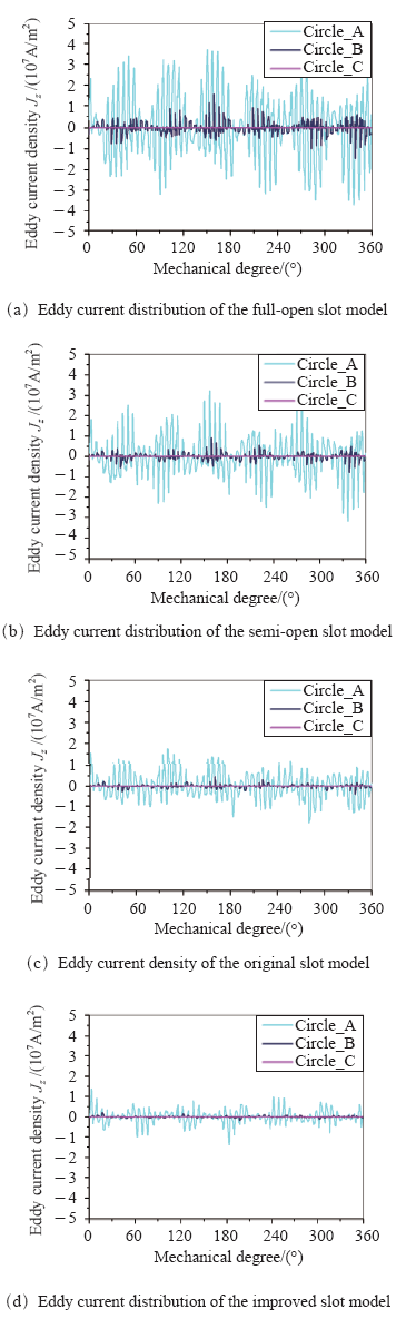
Fig.15 shows the distribution of the rotor eddy current density resulting from the 2-D finite element analysis of the motor with original stator slot. At no-load condition, the rotor eddy current losses caused by the stator slotting are mainly generated on the rotor surface. Three circles which pass through the point A, point B and point C are introduced to analyze the distribution of the eddy current at different position, as shown in Fig.16. Point A, point B and point C are located on the rotor surface, at the center of the rotor bar and at the rotor yoke, respectively.
Fig.15
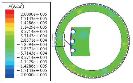
Fig.16
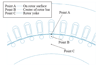
Fig.17 shows the eddy current distribution of the models with different stator slot types at t=0.2s. It can be seen from Fig.17 that eddy current on rotor surface is much larger than that in rotor tooth and rotor yoke. In addition, the permeance caused by stator slotting affects the symmetrical characteristic of the eddy current distribution on rotor surface. Moreover, the eddy current density of the model with the full-open slot is the largest. Furthermore, the eddy current density of the model with closed stator slot is small but not equal to zero. And the eddy current of the model with improved stator slot is smaller than the others.
Fig.17
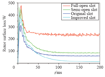
The rotor surface losses of the models with the different slot types are shown in Fig.18. In general, the results are consistent with the eddy current distributions as well as the stator tooth harmonic field. The average values are evaluated from 180ms to 200ms. The analytical results which considered the precious five harmonics and the FEM results are shown in Tab.2. The rotor surface losses of the model with the original slot and the improved slot are calculated to be zero according to the analytical method. As the authors said, the limitation is that the previous analytical method did not consider the highly saturated slot bridge. The difference between the analytical results and the FEM results can be explained because the FEM method considered the magnetic saturation and material nonlinearity. According to the finite element results, the rotor surface loss of the model with improved stator slot is much smaller than that of the open slots and original slots. This is because the slot bridge of the improved stator slot is not easily to be highly saturated.
Fig.18
Tab.2 Analytical and FEM results for the rotor surface losses of the model
| Rotor surface loss/W | ||
|---|---|---|
| Analytical | FEM | |
| Full-open slot | 155.6 | 235.8 |
| Semi-open slot | 71.6 | 89.0 |
| Original slot | 0 | 48.2 |
| Improved slot | 0 | 14.1 |
4 Conclusion
This paper studies the rotor surface losses in submersible motor with different stator slot types including full-open slot, semi-open slot, original closed slot and improved closed slot at no-load condition. Generally, the rotor surface experiences alternating flux components because of a changing permeance caused by the stator slots. And the drops in the flux density caused by slots create losses on the rotor surface.
In this paper, models with four stator slot types are introduced to analyze the rotor surface losses of the submersible motor at no-load condition. Full-open slot and semi-open slot are used for comparison and the improved slot is the optimized slot shape we proposed for reduction of rotor surface losses. According to the analytical method, the Carter Factors of the models with the full-open slot and the semi-open slot are 1.45 and 1.14, respectively. Both Carter Factors of the models with closed slot types are zero. The spatial and time-varying distributions of the tooth harmonic fields caused by stator slotting are presented by analytical method.
The difference between the analytical results and the FEM results can be explained because the FEM method considered the magnetic saturation and material nonlinearity. It is concluded that the rotor surface loss of the model with improved stator slots is much smaller than that of the open slots and original slots. This is because the slot bridge of the improved stator slot is not easily to be highly saturated. The authors believe that the Carter Factor of the closed-stator-slot motor is not equal to 1 because the flux density in the slot bridge is highly saturated due to the narrow and long shape. This gives a good explanation that the stator tooth harmonics as well as the rotor surface losses of the closed-stator-slot motor are not zero. Further work will be done in a later paper.
Appendix
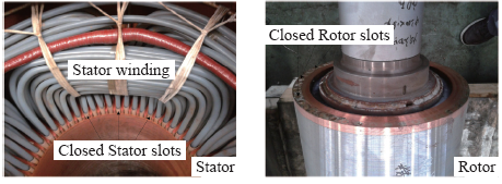
APP.Tab. Specifications of the submersible motor
| Item | Specification |
|---|---|
| Rated power/kW | 30 |
| Rated voltage/V | 380 |
| Pole pairs | 3 |
| Connection type | Y |
| Outer diameter of stator/mm | 590 |
| Inner diameter of stator/mm | 445 |
| Outer diameter of rotor/mm | 443.4 |
| Core length/mm | 68 |
| Number of stator slots | 54 |
| Number of rotor slots | 58 |
参考文献
Stray load losses in induction motors: A challenge to academia
[J].
A study on rotor surface losses in small-to-medium cylindrical synchronous machine
[J].DOI:10.1109/TEC.2012.2211877 URL [本文引用: 2]
Effects of MMF harmonics on rotor eddy-current losses for inner-rotor fractional slot axial flux permanent magnet synchronous machines
[J].DOI:10.1109/TMAG.2011.2173923 URL [本文引用: 2]
Calculation of eddy current losses in axial field permanent magnet machine with coreless stator
[J].DOI:10.1109/TEC.2004.832043 URL [本文引用: 1]
A study on eddy-current losses in rotors of surface permanent-magnet synchronous machines
[J].DOI:10.1109/TIA.2006.870037 URL [本文引用: 1]
Analytical prediction of eddy-current loss in modular tubular permanent magnet machines
[J].DOI:10.1109/TEC.2005.853732 URL [本文引用: 1]
Eddy-current loss in the rotor magnets of permanent-magnet brushless machines having a fractional number of slots per pole
[J].DOI:10.1109/TMAG.2005.854337 URL [本文引用: 1]
Rotor eddy-current loss in permanent magnet brushless AC machines
[J].DOI:10.1109/TMAG.2010.2042963 URL [本文引用: 1]
Two-dimensional analytical permanent-magnet eddy current losses calculation in slotless PMSM equipped with surface-inset magnets
[J].DOI:10.1109/TMAG.2013.2285525 URL [本文引用: 1]
Torque and loss calculation of rotating machines considering laminated cores using post 1-D analysis
[J].
DOI:10.1109/TMAG.2010.2089501
URL
[本文引用: 1]

A post 1-D analysis of laminated cores is developed for estimating the torque and loss in rotating machines. The 1-D nonlinear eddy-current analysis along the thickness of electrical steel sheets is carried out at each element in the main finite-element analysis in order to estimate the loss and the harmonic torques caused by the eddy currents and the hysteresis phenomenon in the core. The proposed method is applied to several kinds of rotating machines. It is revealed that the accuracies of the torque and loss are significantly improved by the proposed method as compared to those of the conventional finite element method without notable increase in the computation time.
A multiplayer 2-D -2-D coupled model for eddy current calculation in the rotor of an axial flux PM machine
[J].
DOI:10.1109/TEC.2012.2192737
URL
[本文引用: 1]
On the rotors of an axial-flux PM machine, NdFeB permanent magnets (PM) are very often placed because of their high energy density. As the NdFeB-magnets are good electric conductive, electric currents are induced in the magnets when they are exposed to a varying magnetic field. This varying magnetic field has two causes: variation of the airgap reluctance due to the effect of stator slots and armature reaction due to the stator currents. As axial-flux PM machines have an inherent 3-D-geometry, full 3-D-finite-element modeling seems necessary to calculate the eddy currents in the PM and to evaluate their corresponding losses. In this paper, however, the 1-D airgap magnetic fields of multiple multilayer 2-D finite-element simulations are combined to a 2-D airgap magnetic field using static simulations. In a subsequent step, this 2-D airgap magnetic field is imposed to a 2-D finite-element model of the PM to calculate the eddy currents and eddy current losses. The main benefit of this multilayer 2-D-2-D coupled model compared to 3-D finite-element modeling is the reduction in calculation time. Accuracy of the suggested multilayer 2-D-2-D coupled model is verified by simulations using a 3-D finite-element model.
Rotor loss analysis of interior permanent motors using combination of 2-D and 3-D finite element method
[J].DOI:10.1109/TMAG.2009.2012817 URL [本文引用: 1]
Eddy current calculation of solid components in fractional slot axial flux permanent magnet synchronous machines
[J].DOI:10.1109/TMAG.2011.2158200 URL [本文引用: 1]
Calculation and analysis of rotor eddy current losses of permanent magnet induction hybrid excited synchronous generator
[J].
Eddy current reduction in hign-speed machines and eddy current losses analysis with multislice time-stepping finite element method
[J].
DOI:10.1109/TMAG.2011.2173915
URL
[本文引用: 2]
The significance of eddy-current in high-speed permanent magnet machines cannot be underestimated in that it has serious implications on the machine's efficiency or even demagnetizes the PMs because of an overheating problem. It is necessary to accurately estimate the eddy-current losses and find an optimal design to minimize the losses and improve the machine's performance. In this paper, the axial segmentation of the PMs is first employed to cut off the eddy-current axial paths. Then, a conductive shield is introduced to smooth the time varying magnetic field in the conductive sleeve and the PMs in order to reduce the eddy-current losses. A nodal method based network-field coupled multislice time-stepping finite element method (TS-FEM) is proposed to analyze the steady-state and dynamic characteristics of the high-speed PM machine; its merit is that sub-block matrixes of the circuit equations are more convenient to be established compared with that of mesh method. Analysis of eddy-current losses in the rotor is reported.
Reduction of rotor eddy current losses in high speed PM brushless machines by grooving retaining sleeve
[J].
DOI:10.1109/TMAG.2013.2243408
URL
[本文引用: 2]
Eddy currents might be significant in the rotor of a high speed permanent magnet brushless machine, especially when a metal retaining sleeve is applied. Various methods have been used to reduce the eddy currents. In this paper, a simple method, by grooving the retaining sleeve, is proposed, such that the flowing path of the eddy currents is obscured and the energy loss is thus suppressed. Circumferential, axial and comprehensive grooving are comparatively studied, particularly on the aspects of loss reduction, sleeve mechanical strength, rotor dynamic balance, and manufacture process complexity. It is proved that the circumferential grooving is the most effective for overall performance improvement and the simplest for practical manufacture with little extra cost.
Design of IPMSM rotor shape for magnet eddy current losses reduction
[J].DOI:10.1109/TMAG.2013.2282473 URL [本文引用: 2]
Reducing harmonic eddy-current losses in the stator teeth of interior permanent magnet synchronous machines during flux weakening
[J].DOI:10.1109/TEC.2009.2033195 URL [本文引用: 2]
High-frequency loss calculation in a smooth rotor induction motor using FEM
[J].DOI:10.1109/TEC.2006.881079 URL [本文引用: 1]
Circuit models for predicting core losses in the stator and rotor of a caged induction machine with sinusoidal supplies
[J].
DOI:10.1109/TMAG.2010.2097582
URL
[本文引用: 1]
This paper proposes parameterized models to predict core losses in the stator and rotor of a caged induction machine. The parameters are identified from results of finite element simulations, using a differential evolution search algorithm. To account for flux distribution and frequency characteristics, it is found that variable flux power coefficients for hysteresis terms are required for both stator and rotor. In addition, a rotor core loss coefficient is necessary. The proposed model is compared with FE results and experimental data.
3-D finite element analysis of additional eddy current losseses in induction motors
[J].
DOI:10.1109/TMAG.2011.2173919
URL
In this paper, an approach based on the three-dimensional finite element analysis is proposed to evaluate additional eddy current losses in induction motors of several MW. Losses produced by induced eddy currents in the end-region of the machine (stator clamping-plates and clamping-fingers) and losses provoked by parasitic leakage fields in the housing and in the metal parts of the cooling-ducts are investigated. Furthermore, excess rotor copper losses produced by higher harmonic fields in the rotor squirrel cage are taken into consideration as well. Comprehensive three-dimensional finite element models have been prepared in order to take these effects precisely into account. A numerical procedure based on nonconforming finite element meshes has been used in order to simplify the modeling procedure and the solving process has been carried out in the frequency domain with the aim of reducing the computational time.
Evaluation of stray load losses in cores and secondary conductors of induction motor using magnetic field analysis
[J].
DOI:10.1109/TMAG.2013.2245642
URL
To develop further higher efficiency induction motors, the reduction of the stray load losses, which are the increase of loss in the load condition relative to that in no-load test condition, should be investigated by using the magnetic field analysis. However, the calculation of the stray load losses using the magnetic field analysis requires high computation cost due to consideration of the slot harmonics in the flux densities, and the large time constant. In this paper, to evaluate the stray load losses in the cores and the secondary conductors of induction motors using the two-dimensional (2-D) magnetic field analysis within practical computation cost, some useful techniques, to mention a few, the nonconforming technique and the simplified time-periodic explicit error correction method, are introduced. Then, the stray load loss of an actual induction motor without skew is evaluated by the developed 2-D magnetic field analysis. It is shown that the calculated no-load losses are almost the same with the measured one, and the stray load losses in the stator core and secondary conductors due to the harmonic components in the secondary current are large.
Three-dimensional eddy current losses modeling in steel laminations of skewed induction machines
[J].
DOI:10.1109/TMAG.2012.2236644
URL
[本文引用: 1]
The effects of skewing on the loss behavior of a megawatt rated slip-ring induction machine are studied. The iron loss evaluation is performed by postprocessing the field solution obtained from a multi-slice finite element model. A novel method to compute the three-dimensional eddy current distribution in the steel sheets is employed for the eddy current analysis. The iron loss models are validated against no-load iron loss measurements. Simulation results under load show that skewing leads to a highly non-uniform iron loss distribution along the machine length. The sum of the iron and copper losses increases slightly compared to a machine with straight rotor bars.
Slot-harmonic fields in closed machines
[J].
DOI:10.3390/s19204356
URL
PMID:31600919
[本文引用: 2]
Modelling and simulation of social interaction and networks are of high interest in multiple disciplines and fields of application ranging from fundamental social sciences to smart city management. Future smart city infrastructures and management are characterised by adaptive and self-organising control using real-world sensor data. In this work, humans are considered as sensors. Virtual worlds, e.g., simulations and games, are commonly closed and rely on artificial social behaviour and synthetic sensor information generated by the simulator program or using data collected off-line by surveys. In contrast, real worlds have a higher diversity. Agent-based modelling relies on parameterised models. The selection of suitable parameter sets is crucial to match real-world behaviour. In this work, a framework combining agent-based simulation with crowd sensing and social data mining using mobile agents is introduced. The crowd sensing via chat bots creates augmented virtuality and reality by augmenting the simulated worlds with real-world interaction and vice versa. The simulated world interacts with real-world environments, humans, machines, and other virtual worlds in real-time. Among the mining of physical sensors (e.g., temperature, motion, position, and light) of mobile devices like smartphones, mobile agents can perform crowd sensing by participating in question-answer dialogues via a chat blog (provided by smartphone Apps or integrated into WEB pages and social media). Additionally, mobile agents can act as virtual sensors (offering data exchanged with other agents) and create a bridge between virtual and real worlds. The ubiquitous usage of digital social media has relevant impact on social interaction, mobility, and opinion-making, which has to be considered. Three different use-cases demonstrate the suitability of augmented agent-based simulation for social network analysis using parameterised behavioural models and mobile agent-based crowd sensing. This paper gives a rigorous overview and introduction of the challenges and methodologies used to study and control large-scale and complex socio-technical systems using agent-based methods.
Design of rotating electrical machines
[M].
