


1 引言
近年来无线输电系统得到越来越多人的关注和熟知,已经成为目前的研究热点。无线输电大致分为三类:微波方式、电磁感应方式和磁耦合谐振方式。微波方式虽可实现远距离和大功率的电能传输,但其传输衰减较为严重,传输效率也不高,难以满足大众的期待。电磁感应方式传输效率很高,但传输距离较短,使其应用受到限制。磁耦合谐振方式的传输距离可达到米级范围,传输效率也较高,激起了人们对无线输电系统的研究热潮。
输出功率、传输距离、频率和效率是磁耦合谐振无线输电系统的主要性能指标,到目前为止,已经有很多文献从拓扑结构的角度对系统进行了分析,但都不是很全面。本文从等效电路的角度详细分析了磁耦合谐振无线输电系统的四种不同的拓扑结构,推导出输出功率与效率的表达式,分别分析了输出功率与频率、距离的关系以及效率与频率、距离的关系,并综合比较了四种拓扑结构的输出功率和效率。
2 磁耦合谐振无线输电的原理
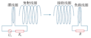
在磁耦合谐振式无线输电系统中,能量的传输是在一个谐振系统内进行的,对谐振系统以外的物体没有影响,实现了较高效率的电能传输。以电路理论来进行分析无线输电中谐振的产生。在通常的非谐振情况下,电路两端电压与电流的相位不同,如果调节输入电源的频率或电路元件(电感L或电容C)的参数,使其相位相同,则整个电路呈现为纯电阻性,此时就会产生谐振。电路在谐振情况下,能量在电感L(能量存储在磁场中)和电容C(能量存储在电场中)间来回循环振荡,电阻R则是消耗能量。图1为磁耦合谐振无线输电系统的基本结构图。
图1
3 磁耦合谐振无线输电的拓扑结构
根据发射端和接收端电路不同的连接方式,磁耦合谐振无线输电系统可以分为四种拓扑结构:串串结构(SS)、串并结构(SP)、并串结构(PS)、并并结构(PP),如图2所示,本文将一一对这四种拓扑结构进行详细分析。
图2
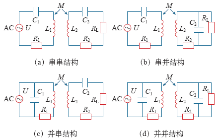
在磁耦合谐振无线输电系统中,发射端和接收端电路都为串联结构的拓扑形式称为串串结构。其中,U为输入电压,R1、R2分别为发射线圈和接收线圈的电阻,L1、L2分别为发射线圈和接收线圈的自感,C1、C2分别为发射线圈和接收线圈的谐振电容,M为线圈间的互感,RL为接收端的负载电阻。
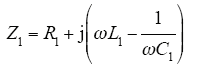
发射端电路的等效阻抗为
接收端电路的等效阻抗为
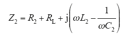
式中,ω为角频率,ω = 2πf。
根据基尔霍夫定律,可得到方程如下
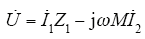
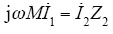
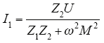
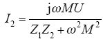
可求得发射和接收线圈中的电流分别为
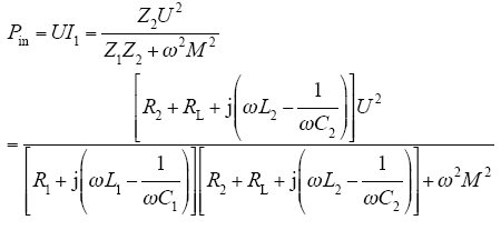
发射功率为
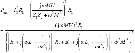
输出功率为
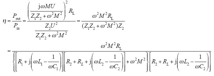
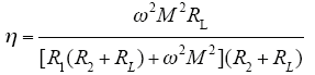
由此,可得传输效率为
互感M计算式为
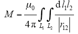
其近似计算公式为
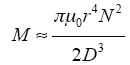
式中,μ0为真空磁导率;r为线圈半径;N为线圈匝数;D为两线圈间距。
当电路产生谐振时,即 

为了便于比较,接下来进行变量替换

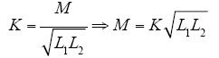

式中,Q为品质因数;K为耦合系数; 
则系统最大传输效率变为
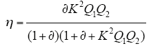
表1 四种拓扑结构的输入功率、输出功率和传输效率
Tab. 1
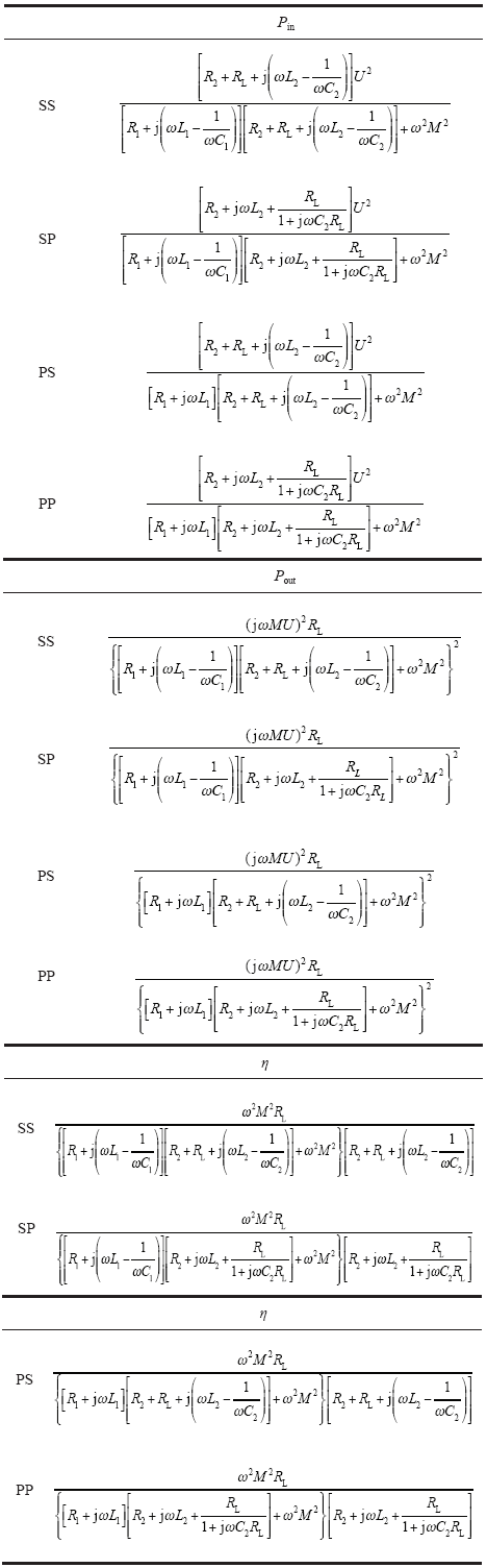 |
表2 变量替换后的四种拓扑结构的最大传输效率
Tab. 2
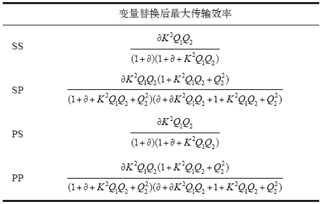 |
通过以上理论推导,得出了磁耦合谐振无线输电系统的四种拓扑结构的输出功率和效率的计算式。通过观察上述表达式可以发现,串串结构和并串结构的最大传输效率表达式相同,串并结构和并并结构最大传输效率表达式相同,因此可知系统最大传输效率只和接收端电路结构有关,与发射端电路结构没有必然联系。由于线圈是给定的,其电感L和电容C都是确定的,虽然线圈电阻会随着频率的改变而改变,但是系统的工作频率在线圈自谐振频率附近,所以R1、R2取谐振频率时的固定值,而本文研究的模型是负载固定不变的情况,即RL也是固定值,因此输出功率Pout和η都只与ω、M有关,而角频率ω又由频率f决定,互感M与D有关,所以Pout和η可以看成是关于f和D的函数。
下面分别通过仿真和实验来验证上述理论分析的正确性,并且研究和分析输出功率和效率关于频率f和距离D的变化规律。
4 仿真分析
本文分别仿真了磁耦合谐振无线输电系统的四种拓扑结构的模型,其参数如下:发射线圈和接收线圈的直径d为0.16m,线圈匝数N为14,电容C为1nF,电感L为67μH,负载RL为50Ω,由f0 = 
拓扑结构一一进行仿真分析,为了清晰直观地观察和分析系统的输出功率Pout和效率η随频率f和距离D的变化规律,依据上述仿真模型,本文利用Matlab仿真得出Pout和η的三维函数图和二维函数图,使变化规律一目了然。
4.1 串串结构仿真分析
图3
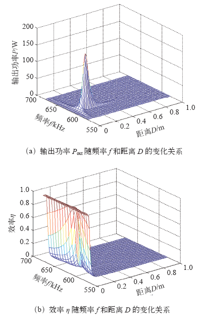
图3
输出功率Pout 和效率η 关于频率和距离D 的变化关系
Fig.3
Relations of the output power Pout and the efficiency η versus frequency f and distance D
图4
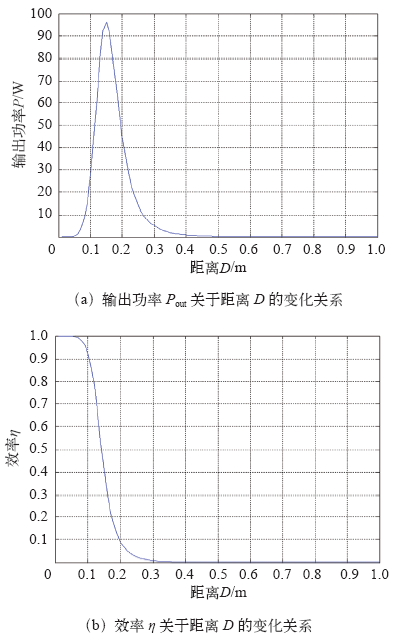
图4
f = 615kHz,输出功率Pout 和效率η 关于距离D的变化关系
Fig.4
Relations of the output power Pout and the efficiency η versus the distance D at f = 615kHz
图5
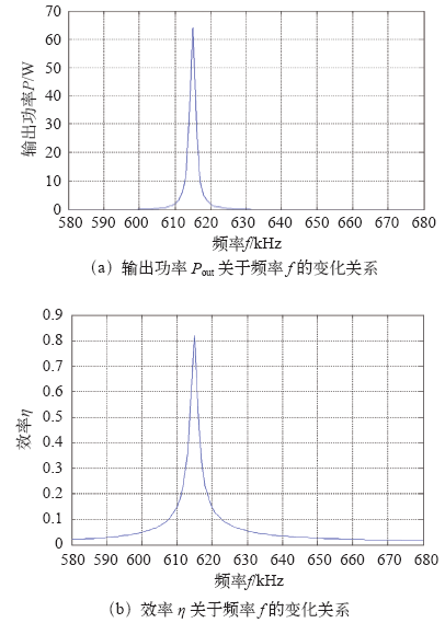
图5
D = 0.12m,输出功率和效率关于f的变化关系
Fig.5
Relations of the output power and the efficiency versus the frequency at D = 0.12 m
由图5可知,在谐振频率点下,输出功率和效率同时达到最大值。
4.2 串并结构仿真分析
图6
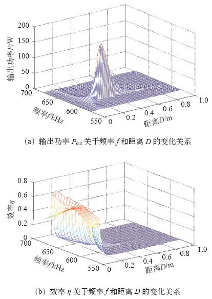
图6
输出功率Pout和效率η关于频率f和距离D的变化关系
Fig.6
Relations of the output power Pout and the efficiency η versus frequency f and distance D
固定频率为谐振频率点615kHz,可以得到输出功率Pout和效率η关于距离D的变化关系,如图7所示。
图7
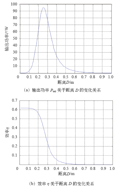
图7
f = 615kHz,输出功率Pout和效率η关于距离D的变化关系
Fig.7
Relations of the output power Pout and the efficiency η versus the distance D at f = 615kHz
由图7可以看出,当频率f = 615kHz,距离D = 0.25m时输出功率达到最大值,效率约为50%,即达到最优匹配。
为了观察输出功率和效率关于频率的变化曲线,固定距离D = 0.21m,得到如图8所示的变化曲线。
图8
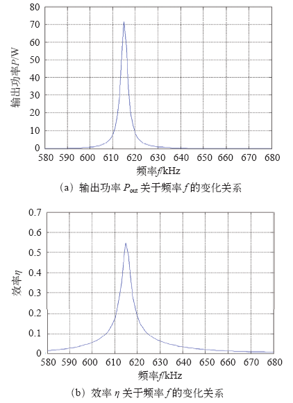
图8
D = 0.21m,输出功率和效率关于f的变化关系
Fig.8
Relations of the output power and the efficiency versus the frequency at D = 0.21m
由图8可知,输出功率和传输效率在谐振频率点时同时达到最大值。
以上仿真与分析结果与文献[8]所描述的一致,证明结果是正确的。
4.3 并串结构仿真分析
并串结构中输出功率Pout和效率η关于频率f和距离D的变化关系如图9所示。
图9
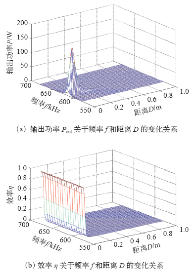
图9
输出功率Pout和效率η关于频率f和距离D的变化关系
Fig.9
Relations of the output power Pout and the efficiency η versus frequency f and distance D
固定频率为谐振频率点615kHz,可以得到输出功率Pout和效率η关于距离D的变化关系,如图10所示。
图10
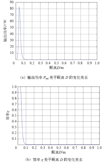
图10
f = 615kHz,输出功率Pout和效率η关于距离D的变化关系
Fig.10
Relations of the output power Pout and the efficiency η versus the distance D at f = 615 kHz
由图10可以看出,当频率等于谐振频率,距离D = 0.05m时,输出功率为最大,效率为50%,系统达到最优匹配。
固定距离D = 0.04m,观察输出功率和效率关于频率的变化规律,如图11所示。
图11
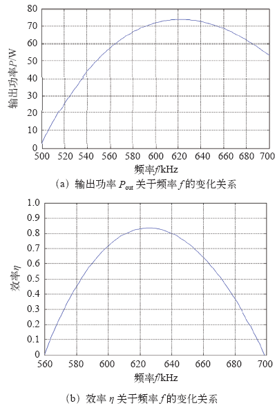
图11
D = 0.04m,输出功率和效率关于频率变化关系
Fig.11
Relations of the output power and the efficiency versus the frequency at D = 0.04m
由图11可知,在在谐振频率点时,输出功率为最大值,效率为50%,达到最优匹配。
4.4 并并结构仿真分析
并并结构中输出功率Pout和效率η关于频率f和距离D的变化关系如图12所示。
图12
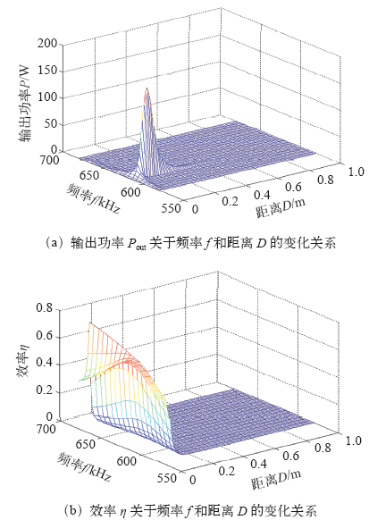
图12
输出功率Pout和效率η关于频率f和距离D的变化关系
Fig.12
Relations of the output power Pout and the efficiency η versus frequency f and distance D
为了得到输出功率和效率关于距离D的变化关系,固定频率为615kHz,得到如图13所示的图形。
图13
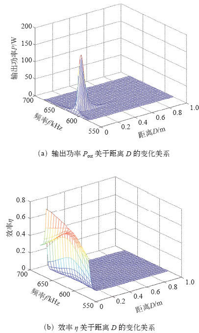
图13
f = 615kHz,输出功率和效率关于距离D的变化关系
Fig.13
Relations of the output power and the efficiency versus the distance D at f = 615 kHz
由以上两图可以看出,在谐振频率点下,当距离为0.09m时,输出功率为最大值,效率为50%,达到最优匹配。
固定距离D = 0.1m,可得到输出功率和效率关于频率f的变化曲线如图14所示。
图14
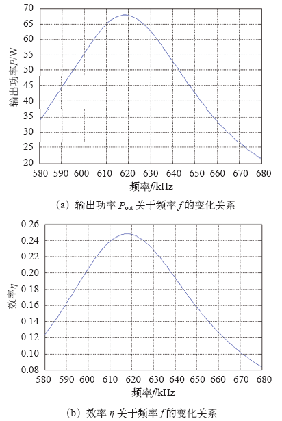
图14
D = 0.1m,输出功率和效率关于频率f变化关系
Fig.14
Relations of the output power and the efficiency versus the frequency f at D = 0.1m
由图14可知,在谐振频率点时,输出功率达到最大值,传输效率为50%,达到最优匹配。
4.5 四种拓扑结构的综合比较
为了更直观的比较磁耦合谐振无线输电系统四种拓扑结构,本文进行了综合研究,得到如下图形。
由图15可知,四种拓扑结构的输出功率随距离D的变化关系大致相同,只是取最大值时传输距离不同,即达到最大值的条件不同。最佳传输距离由大到小为:串并>串串>并并>并串,因此从最佳传输距离和输出功率的角度来看,串并结构优于其他结构。
图15
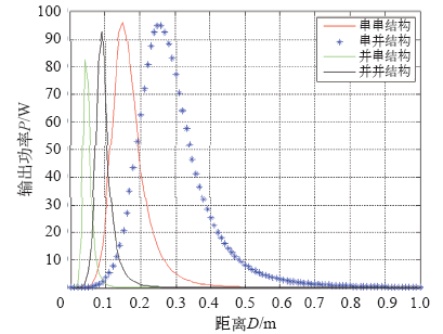
图15
f = 615kHz,四种拓扑结构的输出功率Pout与距离D的变化规律的比较
Fig.15
Comparison between relations of the output power Pout versus the distance D for four topological structures
由图16可以看出,串串结构和并串结构的最大传输效率相同,串并结构和并并结构的最大传输效率相同,即系统最大传输效率只与接收端电路结构有关,仿真结果与前述理论分析一致,证明分析与仿真是正确的。
图16
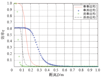
图16
f = 615kHz,四种拓扑结构的效率η与距离D的变化规律的比较
Fig.16
Comparison between relations of the efficiency η versus the distance D for four topological structures
综合比较四种拓扑结构的输出功率和效率,从最佳传输距离的角度来分析,串并结构的性能最优。
5 实验验证
为了验证上述理论分析和仿真的正确性,本文制作了串并结构的实验模型,系统实验仪器主要包括:发射线圈、接收线圈、电路板、信号发生器、功率放大器、示波器、频谱分析仪、功率计、矢量网络分析仪和阻抗分析仪等。发射线圈和接收线圈各有14匝,采用完全相同的两个线圈,直径均为0.16m,发射端与电容构成串联电路,接收端与电容构成并联电路,并使得线圈接口与仪器接口相匹配,系统传输距离为0.21m,负载RL为50Ω,以频率为变量,观察和分析输出功率和效率的变化规律。实验实物如图17所示。
图17
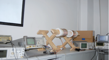
利用信号发生器产生不同频率的正弦波信号,经R&SBBA100功率放大器放大后加载到源线圈,为扣除源线圈对输入能量的反射,事先将源线圈接到网络分析仪R&S ZNB上进行端口特性测试,可以得到源线圈的S参数和反射系数,据此就可以得到输入功率,负载线圈连接功率计,通过功率计测量输出功率,二者之比计算得到系统的传输效率。测量并计算得到串并结构的输出功率和传输效率的实验值见表3。
表3 串并结构的输出功率和效率实验值
Tab.3
| 频率f / kHz | 输出功率Pout / W | 效率η |
|---|---|---|
| 610 | 0.08 | 0.01 |
| 615 | 0.23 | 0.05 |
| 620 | 1.34 | 0.08 |
| 624 | 3.78 | 0.12 |
| 628 | 49.3 | 0.34 |
| 630 | 62.3 | 0.451 |
| 632 | 30.2 | 0.22 |
| 636 | 2.54 | 0.1 |
| 640 | 0.15 | 0.07 |
| 650 | 0.01 | 0.02 |
| 660 | 0 | 0 |
从表3可以看出,串并结构的输出功率和效率在频率为630kHz左右时同时达到最大值,此频率为实际的谐振频率点,与前面理论计算的615kHz不完全一致,这是由于在实际系统中存在杂散电感和杂散电容,以及实验设备的老化等原因造成的。
将输出功率和效率的实验值与理论值进行比较可得到图18所示图形。
图18
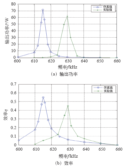
图18
输出功率和效率的实验值与理论值比较
Fig.18
Comparison between the experimented values and the theoretical values of the output power
从图18可以看出,实验值与仿真值总体上是一致的,都是在频率谐振点达到最大值,验证了理论分析的正确性。
6 结论
本文从等效电路的角度对磁耦合谐振无线输电系统的四种拓扑结构进行了详细的分析,得到以下结论:
(1)在谐振频率点附近,四种拓扑结构的输出功率都达到最大值,并且其传输效率为50%,实现最优匹配。
(2)固定频率,四种拓扑结构的输出功率都在某一距离下达到最大值,效率为50%,此距离为最佳传输距离。
(3)四种拓扑结构的传输效率在近距离下较高,但随着距离增大,传输效率急剧下降。
(4)系统最大传输效率只与接收端电路结构有关,与发射端电路没有必然联系。
(5)从最佳传输距离的角度分析,串并结构的性能最优。
参考文献
Wireless power transfer via strongly coupled magnetic resonances
[J].
DOI:10.1126/science.1143254
URL
PMID:17556549
[本文引用: 1]

Using self-resonant coils in a strongly coupled regime, we experimentally demonstrated efficient nonradiative power transfer over distances up to 8 times the radius of the coils. We were able to transfer 60 watts with approximately 40% efficiency over distances in excess of 2 meters. We present a quantitative model describing the power transfer, which matches the experimental results to within 5%. We discuss the practical applicability of this system and suggest directions for further study.
金属障碍物对磁耦合谐振无线电能传输系统的影响
[J].
Impact of metallic obstacles on MCR-based WPT systems
[J].
Efficiency analysis and optimization on magnetic resonance coupled wireless transfer system
[J].
DOI:10.3390/s16081219
URL
PMID:27527169
[本文引用: 1]
High-efficiency power transfer at a long distance can be efficiently established using resonance-based wireless techniques. In contrast to the conventional two-coil-based inductive links, this paper presents a magnetically coupled fully planar four-coil printed spiral resonator-based wireless power-transfer system that compensates the adverse effect of low coupling and improves efficiency by using high quality-factor coils. A conformal architecture is adopted to reduce the transmitter and receiver sizes. Both square architecture and circular architectures are analyzed and optimized to provide maximum efficiency at a certain operating distance. Furthermore, their performance is compared on the basis of the power-transfer efficiency and power delivered to the load. Square resonators can produce higher measured power-transfer efficiency (79.8%) than circular resonators (78.43%) when the distance between the transmitter and receiver coils is 10 mm of air medium at a resonant frequency of 13.56 MHz. On the other hand, circular coils can deliver higher power (443.5 mW) to the load than the square coils (396 mW) under the same medium properties. The performance of the proposed structures is investigated by simulation using a three-layer human-tissue medium and by experimentation.
Transfer efficiency optimal control of magnetic resonance coupled system of wireless power transfer based on frequency control
[J].DOI:10.1007/s11431-011-4380-6 URL [本文引用: 1]
Analysis, experimental results, and range adaptation of magnetically coupled resonators for wireless power transfer
[J].
DOI:10.1109/TIE.2010.2046002
URL
[本文引用: 1]
Wireless power technology offers the promise of cutting the last cord, allowing users to seamlessly recharge mobile devices as easily as data are transmitted through the air. Initial work on the use of magnetically coupled resonators for this purpose has shown promising results. We present new analysis that yields critical insight into the design of practical systems, including the introduction of key figures of merit that can be used to compare systems with vastly different geometries and operating conditions. A circuit model is presented along with a derivation of key system concepts, such as frequency splitting, the maximum operating distance (critical coupling), and the behavior of the system as it becomes undercoupled. This theoretical model is validated against measured data and shows an excellent average coefficient of determination (R(2)) of 0.9875. An adaptive frequency tuning technique is demonstrated, which compensates for efficiency variations encountered when the transmitter-to-receiver distance and/or orientation are varied. The method demonstrated in this paper allows a fixed-load receiver to be moved to nearly any position and/or orientation within the range of the transmitter and still achieve a near-constant efficiency of over 70% for a range of 0-70 cm.
Maximizing air gap and efficiency of magnetic resonant coupling for wireless power transfer using equivalent circuit and neumann formula
[J].
DOI:10.1109/TIE.2011.2112317
URL
[本文引用: 1]
The progress in the field of wireless power transfer in the last few years is remarkable. With recent research, transferring power across large air gaps has been achieved. Both small and large electric equipment have been proposed, e. g., wireless power transfer for small equipment (mobile phones and laptops) and for large equipment (electric vehicles). Furthermore, replacing every cord with wireless power transfer is proposed. The coupled mode theory was proposed in 2006 and proven in 2007. Magnetic and electric resonant couplings allow power to traverse large air gaps with high efficiency. This technology is closely related to electromagnetic induction and has been applied to antennas and resonators used for filters in communication technology. We have studied these phenomena and technologies using equivalent circuits, which is a more familiar format for electrical engineers than the coupled mode theory. In this paper, we analyzed the relationship between maximum efficiency air gap using equivalent circuits and the Neumann formula and proposed equations for the conditions required to achieve maximum efficiency for a given air gap. The results of these equations match well with the results of electromagnetic field analysis and experiments.
磁耦合谐振式无线电能传输系统串并式模型研究
[J].Wireless power transmission system via magnetic resonance coupling displays its superiority in its higher efficiency, longer range and greater power output. This paper conducts research on series-parallel (SP) model, by analyzing the effects that the distance between the coils, operation frequency and load resistance may have on the efficiency and the output power from the view of equivalent circuits, and the expression of efficiency and power was obtained. Calculated by the Matlab, the results show that the frequency of the best efficiency point and maximum power point coincide under the condition of changing system frequency only. Compared with the efficiency, the output power is more sensitive to frequency changes. A wireless power transmission system with series-parallel structure via magnetic resonance coupling is designed and created in this paper, and the correctness of the aforementioned analyses is verified through the experimental results.
Study on serial-parallel model in MCR-based WPT systems
[J].Wireless power transmission system via magnetic resonance coupling displays its superiority in its higher efficiency, longer range and greater power output. This paper conducts research on series-parallel (SP) model, by analyzing the effects that the distance between the coils, operation frequency and load resistance may have on the efficiency and the output power from the view of equivalent circuits, and the expression of efficiency and power was obtained. Calculated by the Matlab, the results show that the frequency of the best efficiency point and maximum power point coincide under the condition of changing system frequency only. Compared with the efficiency, the output power is more sensitive to frequency changes. A wireless power transmission system with series-parallel structure via magnetic resonance coupling is designed and created in this paper, and the correctness of the aforementioned analyses is verified through the experimental results.
