

1 Introduction
Since the invention of NdFeB magnets about 35 years ago [1], permanent magnet (PM) machines have been widely employed for many applications, such as automotive, aerospace, domestic appliances, industrial automation and renewable energy, etc. due to high torque density and high efficiency [2,3,4]. Most successful commercial examples include PM machines used in servo drives, Toyota Prius hybrid and Nissan Leaf electric vehicles, as well as Siemens wind power generation.
However, relatively high cost and potential supply issue of rare-earth magnets are currently major concerns, at least outside China. Less or no rare-earth magnet machines are being seriously considered and investigated [5,6,7,8,9,10], including PM assisted synchronous reluctance machines with reduced NdFeB magnets or employing ferrite magnets [10,11,12,13,14,15]. Conventional electrical machines, such as induction [16,17,18,19,20,21,22], switched reluctance [9,23-25], synchronous reluctance [26,27,28], wound field synchronous machines [29,30,31,32,33,34,35,36,37,38], are being re-examined, while new and novel machines, such as stator wound field synchronous (SWFS) machines [39,40,41,42,43,44,45,46,47,48,49,50,51,52,53,54,55,56,57,58,59,60,61,62,63,64,65,66,67,68,69,70,71,72], are being developed and will be overviewed in this paper. Two recent successful commercial examples are probably ABB’s synchronous reluctance machines for industrial drives and Tesla motors’induction machines.
Conventional rotor wound field synchronous (RWFS) machines are actually very mature technology and commonly used in very high power hydro-electric generators. They offer the advantages of low idle loss, no use of rare-earth magnet, no potential irreversible demagnetization issue of the magnet, and easy to control etc. They are currently extensively exploited for other applications [29,30,31,32,33,34,35,36,37,38] and have been re-emerged in various applications, such as domestic appliances, electric vehicles, aerospace, wind power generators, and high temperature superconducting machines etc. They are commercially employed in the Enercon’s direct-drive wind power generators and Continental’s electric and hybrid electric vehicles (EVs/HEVs) machines. However, it is well known that RWFS machines have lower torque density and lower efficiency than the PM machines although when the power is higher, they may become more competitive. Further, in these conventional RWFS machines, slip-rings/brushes are usually required in order to supply the DC power to the rotor, which have restricted their potential wider applications since slip-rings/brushes require regular maintenance.
Stator wound field synchronous (SWFS) machines have a set of DC field excitation windings placed on the stator together with AC armature windings and a salient pole rotor without any coils or magnets [39,40,41,42,43,44,45,46,47,48,49,50,51,52,53,54,55,56,57,58,59,60,61,62,63,64,65,66,67,68,69,70,71,72]. Therefore, they do not need slip-rings/brushes, as required in the conventional RWFS machines. Thus, the rotor robustness and reliability of SWFS machines have potential to be better and their maintenance cost has potential to be low. Moreover, compared with RWFS machines, better thermal management can be achieved in SWFS machines since all excitation sources are mounted on the stator.
This paper overviews recent development in novel SWFS machines. It will describe the operation principle and various novel machine topologies of SWFS machines, and compare their relative merits and demerits, electromagnetic performance, with particular reference to their torque capabilities. The paper can be considered as a companion paper to Ref. [8] in which only one special type of SWFS machines, i.e. variable flux reluctance machines (VFRMs), are reported, in terms of the stator slot and rotor pole combinations, electromagnetic performance, acoustic noise and vibration, as well as efficiency maps.
It should be noted that all the machines described in this paper are globally optimized for maximum torque using the finite element method based on generic algorithm. Further, two types of specification, one is a small machine with outside diameter and axial length of 90mm and 25mm respectively and another one is the Toyota Prius 2010 interior permanent magnet (IPM) machine, are interactively used throughout the comparison.
2 Topologies of SWFS Machines
SWFS machines are a type of special synchronous machines with DC field excitation on the stator. The stator may be similar to that of a conventional AC machine, or more commonly has salient poles with concentrated non-overlapping windings which have short end-windings. The rotor has no magnets or coils and is similar to that of a switched reluctance machine or a synchronous reluctance machine, but a salient pole rotor is more commonly employed together with a salient pole stator with AC and DC coils wound directly on the stator poles. Therefore, SWFS machines are usually a type of doubly salient pole machines. In general, a 3-phase SWFS machine can be fed from a standard 3-phase inverter bridge with bipolar currents, while standard pulse-width modulation (PWM) techniques, e.g. space vector PWMs, and well known vector controls can be employed [8].
Various SWFS machines may be derived directly from switched reluctance machines [73,74], as shown in Ref.[8] by discomposing a unipolar phase current waveform into DC and fundamental sinusoidal current components while neglecting other high order current harmonics. However, they may also be directly converted from stator PM machines [75,76], as will be shown in this paper.
Stator PM machines have PMs on the stator. Many stator PM machine topologies are available [75]. All the PMs in these PM machines can be replaced by DC coils, albeit with introduction of iron cores to the DC coils to improve the magnetic circuit, and hence, many SWFS machine topologies can be derived, e.g. SWFS switched flux machines and SWFS doubly salient machines can be developed from switched flux PM (SFPM) machines and doubly salient PM (DSPM) machines, as illustrated in Fig. 1 and Fig. 2, respectively. For simplicity, in the following discussions, “F” stands for field winding, “A” stands for armature winding, while the number after F or A represents the coil pitches in terms of slot-pitch. By way of example, a conventional SFPM machine can be converted to a F2A2 SFWS machine with DC field and AC armature windings both having 2 slot-pitches, Fig.1a [45]. A SWFS machine with DC field and AC armature windings having 1 and 3 slot-pitches, respectively, is derived from a sandwiched SFPM machine, Fig. 1b.
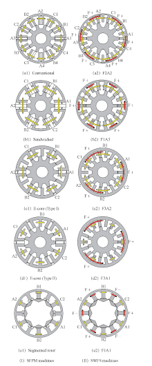
Fig.1
Alternate SWFS machine topologies derived from stator PM machines, SFPM machines
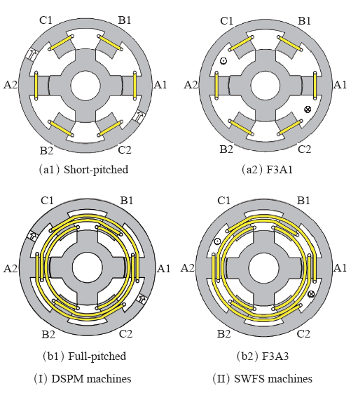
Fig.2
Alternate SWFS machine topologies derived from stator PM machines, DSPM machines
Based on different armature winding arrangements, there exist two types of E-core SFPM machines. In the typical E-core SFPM machine (Type I), armature coils are wound on the stator teeth having PMs, as shown in Fig.1(c1). For the E-core SFPM machine type II, armature coils are wound on the stator teeth without PMs, as shown in Fig.1 (d1). When the DC coils replace the PMs in these two types of SFPM machines, two WFSF machines having the same field coil pitch of 3 slot-pitches and the different armature coil pitches of 2 and 1 slot-pitches/pitch are obtained, as shown in Fig. 1(c2) and Fig.1(d2), respectively.
Unlike the sandwiched and E-core SFPM machines, the segmented rotor SWFS machine, Fig.1(e2) [47,48], is proposed before the segmented rotor SFPM machine, Fig.1(e1). However, the segmented rotor SWFS machine can still be regarded as a machine derived from the segmented rotor SFPM machine. As can be seen, the segmented rotor SWFS machine employs short-pitched field and armature coils. This can be an advantage in the cost-sensitive applications.
Similar to the SFPM machines, the DC coils can replace the PMs in other stator-PM machines. As shown in Fig.2, a SWFS machine having field and armature windings of 3 coil-pitches and 1 coil-pitch respectively can be derived from the conventional short-pitched DSPM machine. This full-pitched SWFS machine is mainly used in generator applica-tions[40,41,50,51]. However, the full-pitched SWFS machine has significantly increased end-winding length.
Short-pitched SWFS machines are competitive in cost-sensitive applications due to low copper usage and compact size. In addition to the segmented rotor SWFS machine, variable flux reluctance machines (VFRMs) are also a SWFS machine employing short-pitched field and armature coils [54,55,56,57,58,59,60,61,62,63,64,65], as mentioned earlier and shown in Fig.3(a2) and Fig.3(b2). They can also be derived from the corresponding machines with PMs in the stator yoke or poles, Fig.3(a1) and Fig.3(b1). Actually they can also be converted from the original switched reluctance machines having all poles or alternate poles wound, Fig.3(a3) and Fig.3(b3), respectively. Compared with the segmented rotor SWFS machine, the VFRM type of SWFS machines has higher torque density, lower torque ripple and much simpler rotor structure. However, although non-overlapping windings are employed for the field and armature windings individually, the over-lapped field and armature coils in Fig.3(a2) lead to more complicated winding configuration and longer end-windings. Hence, a completely non-overlapping SWFS machine, Fig.3(b2), is desirable. Their performance will be compared later in this paper.
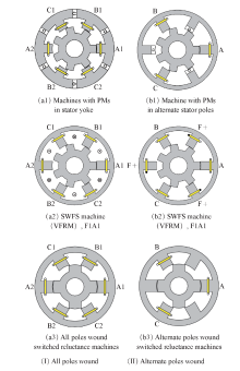
Fig.3
Alternate SWFS machine topologies derived from all poles wound and alternate poles wound stator PM machines and switched reluctance machines
All SWFS machine topologies can be summarized by a 3×3 matrix according to the coil-pitches of field and armature windings although there may be more than one type, e.g. Fig.1(d2) and Fig.2(a2) for F3A1, Fig.1(e2) and Fig.3(a2) for F1A1. However, other SWFS machines having field and armature windings of 1 and 2 (in F1A2, Fig.4), 2 and 1 (in F2A1), 3 and 2 (in F2A3) coil-pitches have long end-windings, which is a big disadvantage in cost-sensitive applications due to the increased copper usage and machine size. Similar to the E-core SFPM machine type II (F3A1), the torque densities in these SWFS machines are low due to the magnetic saturation and flux leakage in the stator.
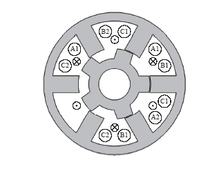
In cost-sensitive applications, the single-phase SWFS machines have the advantage in terms of the power device costs compared with the multi-phase SWFS machines. A single-phase 8-slot/4-pole SWFS machine, F2A2, has been successfully commercialized for more than 10 years [43,44], as shown in Fig.5. Compared with an induction machine, this machine exhibits higher efficiency and power factor. However, the performance of this machine can be improved further by employing a single-phase SWFS machine of F1A3 type [66].
It is worth noting that for SWFS machines having bipolar coil flux-linkage, the coil has the positive or negative maximum flux-linkage when the D-axis aligns with the coil, as shown in Fig.6. Meanwhile, for the SWFS machines having unipolar coil flux-linkage, the coil has the maximum or minimum flux-linkage when the D-axis aligns with the coil, as shown in Fig.7.
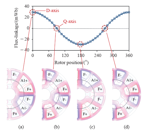
Fig.6
Open-circuit field distributions and typical flux-linkage waveform of single bipolar coil in a F1A3 SWFS machine
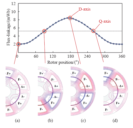
Fig.7
Open-circuit field distributions and typical flux-linkage waveform of single unipolar coil in a F1A1 SWFS machine
3 Comparison of Various SWFS Machines
3.1 Comparison of Variable Flux Reluctance Machines (VFRM) Having Alternate Rotor-Pole Numbers
As mentioned earlier, VFRMs are a type of SWFS machines, as shown in Fig.3(a2). To ease the comparison the term of VFRM is still employed. The flux linkage, back-EMF, cogging torque, and static torque waveforms, as well as variation of torque against the copper loss of 6-stator slot VFRMs having different rotor pole numbers are compared in Fig.8. The flux linkage waveforms are unipolar when the rotor pole numbers are even, and bipolar when the rotor pole numbers are odd. In order to explain the back-EMF variations between different stator-slot/rotor-pole Ns/Nr combinations, it is necessary to consider the fundamental electrical frequency which depends on the rotor pole number. For example, the 6/7 stator/rotor-pole VFRM exhibits higher fundamental back-EMF than the 6/5 stator/rotor-pole VFRM despite of a lower fundamental flux-linkage. It is due to that the fundamental electrical frequency of 7-rotor pole VFRM is 1.4 times of the one for 5-rotor pole VFRM at the same speed. As in all SWFS machines, the cogging torque is defined as the static torque when DC field windings are excited with the DC currents while the AC armature coils are not excited. For machines having an odd number of rotor pole, the back-EMF waveform is more sinusoidal, the cogging torque and torque ripple are lower. Overall, the 6-stator-slot/7-rotor-pole VFRM exhibits the best electromagnetic performance. Similar conclusions can be obtained for the 12-stator slot VFRM machines. More details may be found in Ref.[60-62].
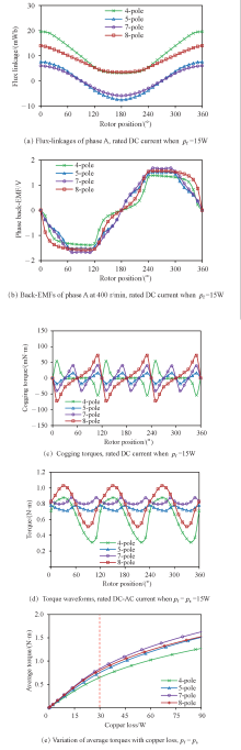
Fig.8
Electromagnetic performance of 6 stator slot VFRMs with different rotor pole numbers pf = field winding copper loss, pa = armature winding copper loss
3.2 Comparison of Non-overlapping Winding SWFS Machines Having Alternate Stator-Slot and Rotor-Pole Numbers [68]
For Fig.3(b2) type of 12-stator-slot SWFS machines having non-overlapping windings and different stator-slot/rotor-pole Ns/Nr combinations, their electromagnetic performance are compared in Fig.9. Similar to VFRMs, when the rotor pole number is odd, the back-EMF waveform is more sinusoidal, the cogging torque and torque ripple are lower. As shown in Fig.10, when the currents are low and armature current = field current<30A for 6-stator-slot machines and <50A for 12-stator-slot machines, their torque capabilities are similar except for the 4-rotor-pole machine. However, when the current are high, the machines with odd rotor-pole numbers become much better, and the corresponding 6-stator-slot machines can produce higher torque than the 12-stator-slot machines.
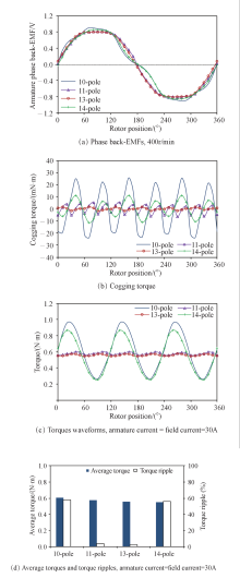
Fig. 9
Comparison of non-overlapping 12 stator slot F1A1 SWFS machines having different rotor pole numbers, field current = 30 A
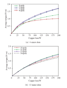
Fig.10
Variation of average torque with copper loss of non-overlapping F1A1 SWFS Machines having different stator-slot and rotor-pole numbers, field winding copper loss=armature winding copper loss
3.3 Comparison of Non-overlapping VFRM and SWFS Machines
Both VFRM and F1A1 SWFS machines are non-overlapping winding F1A1 SWFS machines, as discussed in the previous two sections. The best VFRM and F1A1 SWFS machines are selected for comparison and their torque against the copper loss variations are shown in Fig. 11. It is shown that the VFRM machine has better torque capability than the F1A1 SWFS machine although the over-lapped field and armature coils in the VFRM machine will lead to longer end-windings.
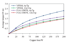
Fig.11
Comparison of non-overlapping VFRM and SWFS machines, field winding copper loss=armature winding copper loss
3.4 Comparison of Non-overlapping SWFS Machines Having Segmented and Conventional Rotors
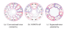
Most SWFS machines have overlapping windings and conventional salient rotors. Overlapping windings result in high material cost and low torque density due to long end-windings. For non-overlapping windings, two types of machines have different polarities of stator DC coil excitation, consequent pole type field excitation, Fig. 12a, and alternate polarity type field excitation Fig.12b for NSWFS-AP and Fig.12c for segmented rotor. As mentioned earlier, segmented rotor is hard to fabricate and has low torque density and high torque ripple, as will be shown in this section, while the conventional salient rotor has high torque density and low torque ripple except for the NSWFS-AP machine which has very poor performance.
The average torque and torque ripple, as well as torque-copper loss curves of the four investigated NSWFS machines, an optimized 12-slot/5-pole NSWFS-AP machine (the torque density is the highest among 12-slot NSWFS-AP machines, according to Ref.[69]), and an optimized 12-slot/8-pole SNSWFS machine (the torque density is the highest among 12-slot SNSWFS machines, according to Ref.[47,48]) are compared in Fig. 13 and Fig.14, respectively. As can be seen, the NSWFS-AP machine shows very low torque density due to the inappropriate field coil polarity. All NSWFS machines show higher average torque than the SNSWFS machine when the copper loss is less than 100W. When the copper loss is 60 W, the average torque of the 11-pole NSWFS machine is 15.2% higher than that of the SNSWFS machine. It should be noticed that the torque ripple of the SNSWFS machine is 32.4%, while the torque ripples of the 11- and 13-pole machines are only 3.5% and 3.3%, respectively, when the copper loss is 60W.
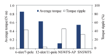
Fig.13
Average torques and torque ripples of non-overlapping SWFS machines, armature current = field current=30A, copper
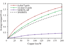
Fig.14
Variation of average torque with copper loss of non-overlapping SWFS machines, armature current = field current
3.5 Comparison of Various SWFS Machines with Toyota Prius IPM Machine
Six SWFS machines having best stator slot and rotor pole combinations (12s/8p segmented rotor F1A1, 12s/11p VFRM, 12s/11p salient-pole rotor F1A1, 24s/14p F2A2, 18s/10p F1A3, 12s/8p F3A1) are chosen and compared with Toyota Prius IPM 2010 machine of the same size (stator outer diameter=264mm, axial length = 50.8mm, air-gap length=0.73mm, all armature and field currents are the same under the same current density), as shown in Fig.15. All SFWS machines have been optimized to achieve the maximum average torque when the total current density is 26.8A/mm2, the same as that of IPM machine. When the current density is 26.8A/mm2, the average torques and torque ripples of machines are shown in Fig.16. Fig.17 compares the average torque and material usage efficiencies (based on the purchase prices of materials in late 2013) under different current densities. The SWFS machine with segmented rotor has lower average torque and higher torque ripple than other machines. F2A2-14 pole and F1A3-10 pole machines exhibit relatively higher torque capability, F1A1-11 pole machine has relatively lower torque density but short end-winding as mentioned before, F1A1-11 pole and F2A2-14 pole machines show the lowest torque ripples among these machines. All SWFS machines show similar good material usage efficiency when the end-windings are considered, higher than the IPM machine, but their torque densities are all lower than that of the IPM machine. Overall, the SWFS machines, of which sums of field and armature winding pitches are even integers, exhibit good torque capabilities. Among these SWFS machines, the torque capabilities of non-overlapping winding machines are still smaller than those of other overlapping winding machines, partially due to the fact that the end-windings are not considered in the comparison of torque density.
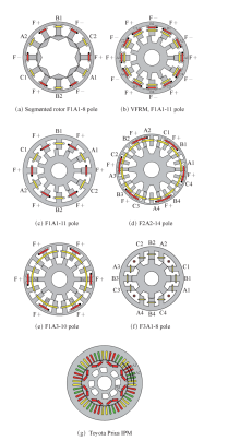
Fig.15
Various SWFS machines used for comparison with Toyota Prius IPM machine
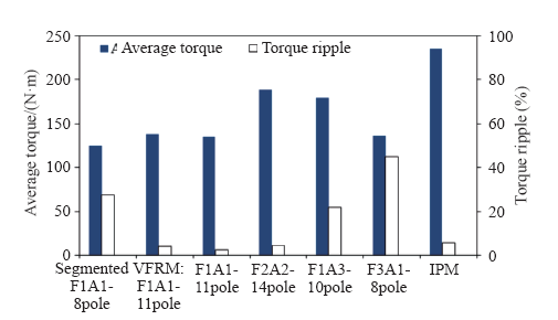
Fig.16
Comparison of average torque and torque ripple of SWFS machines and Toyota Prius IPM machine, current density=26.8A/mm2
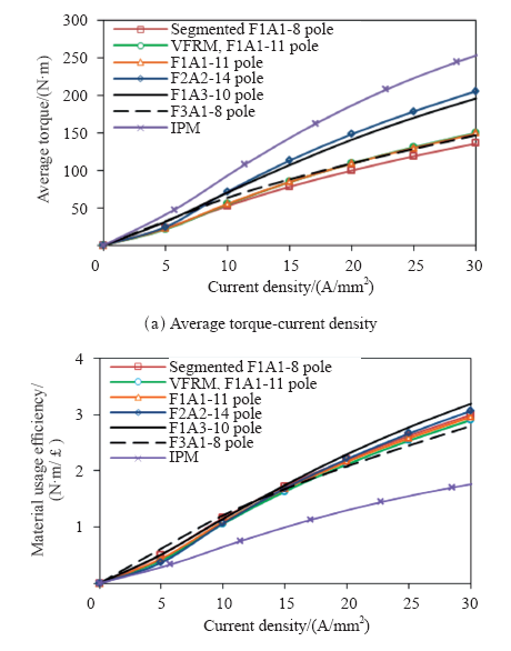
Fig.17
Comparison of torque and material usage efficiency of various SWFS machines and Toyota Prius IPM machine
4 Recent Development in Stator Wound Field Synchronous Machines - Partitioned Stator Wound Field Machines
In the foregoing SWFS machines, both DC field and AC armature windings are on the stator and there is no need of slip-rings/brushes, while the salient pole rotor is very simple and robust without coils or magnets. However, there is a stator space conflict between the field and armature windings. In the partitioned stator (double stator) machines, the field winding is moved to a second stator, allowing for increased copper spaces for both field and armature windings and better utilisation of the machine inner space within the same machine volume to increase the torque density. Fig.18 and Fig.19 show the conventional single and partitioned stator SWFS machines [71] and VFRMs [72]. Different from the conventional double stator machines [77] in which both stators are usually identical, one stator hosts the field windings and the other stator hosts the armature windings in partitioned stator machines. Although the rotor in the partitioned stator machines is made up of iron pieces, the operation principle is the same as that in the conventional single stator SWFS machines. The magnetic field generated by the field windings in one stator will be modulated by the rotor iron pieces and then enter the other stator teeth to link with the armature windings and produce the effective flux-linkage. As shown in Fig. 20 and Fig. 21, both the partitioned stator machines exhibit larger torque capability than the corresponding conventional single stator machines over the whole investigated operation range.
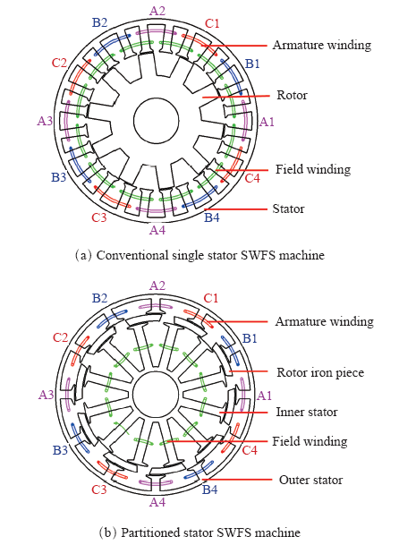
Fig.18
Cross-section of conventional single and partitioned stator SWFS machines
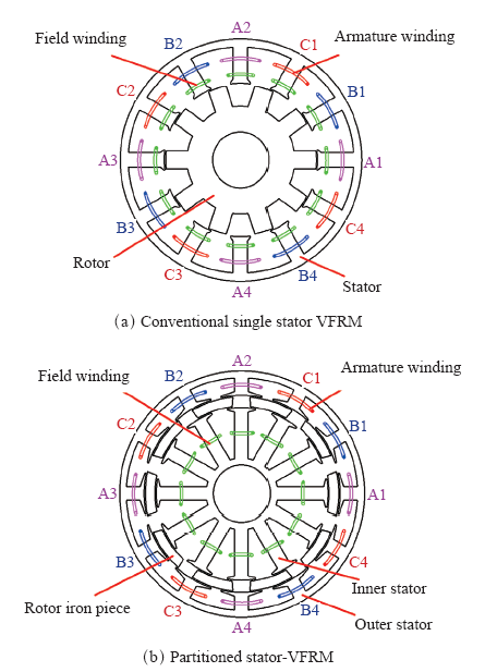
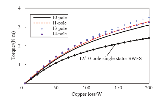
Fig.20
Variation of average electromagnetic torque with total copper loss in conventional single and partitioned stator SWFS machines
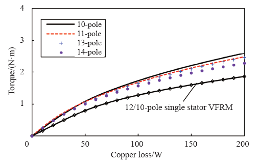
Fig.21
Variation of electromagnetic torque with total copper loss in conventional single and partitioned stator VFRMs
5 Conclusions
Various novel stator wound field machines have been derived from switched reluctance machines and/or stator PM machines. Alternate machine topologies and operation principles are described and their electromagnetic performance are compared, with particular reference to their torque capability.
The SWFS machine with segmented rotor has lower average torque and higher torque ripple than other machines. F2A2-14 pole and F1A3-10 pole machines exhibit relatively higher torque capability, F1A1-11 pole machine has relatively lower torque density but short end-winding, whilst F1A1-11 pole and F2A2-14 pole machines show the lowest torque ripples among these machines. All SWFS machines show similar good material usage efficiency, higher than the IPM machine, but their torque densities are all lower than that of the IPM machine.
In comparison with switched reluctance machines, VFRM type SWFS machines can potentially achieve similar torque density, with significantly reduced torque ripple, acoustic noise and vibration, whilst more feasible stator/rotor combinations can be employed [8].
In general, the partitioned stator machines exhibit larger torque capability than the conventional single stator machines.
Compared with the RWFS machines, SWFS machines can achieve similar torque capabilities, but eliminate the use of slip-rings/brushes. A good torque capability, ~70% torque density compared with IPM machines, and low torque ripple can be achieved.
As synchronous machines, conventional 3-phase full bridge inverters can be employed albeit with DC field excitation, together with vector control and space vector PWM techniques.
(编辑:郭丽军)
参考文献
Thirty four years with NdFeB-invention, development and future
[C].
Novel permanent magnet machines- challenges and applications
[C].
Permanent magnet machines for traction applications. in Encyclopedia of Automotive Engineering
[M].
Design, analysis, and control of interior PM synchronous machines
[M].
Automotive electric motors, generators, and actuator drive systems with reduced or no permanent magnets and innovative design concepts
[J].DOI:10.1109/TIE.2014.2307839 Magsci [本文引用: 1]
Automotive electric propulsion systems with reduced or no permanent magnets: an overview
[J].
DOI:10.1109/TIE.2014.2301754
Magsci
[本文引用: 1]

Hybrid and electric vehicle technology has seen rapid development in recent years. The motor and the generator are at the heart of the vehicle drive and energy system and often utilize expensive rare-earth permanent magnet (PM) material. This paper reviews and addresses the research work that has been carried out to reduce the amount of rare-earth material that is used while maintaining the high efficiency and performance that rare-earth PM machines offer. These new machines can use either less rare-earth PM material, weaker ferrite magnets, or no magnets; and they need to meet the high performance that the more usual interior PM synchronous motor with sintered neodymium-iron-boron magnets provides. These machines can take the form of PM-assisted synchronous reluctance machines, induction machines, switched reluctance machines, wound rotor synchronous machines (claw pole or biaxially excited), double-saliency machines with ac or dc stator current control, or brushless dc multiple-phase reluctance machines.
High power wind generator designs with less or no PMs: An overview
[C].
Novel stator electrically field excited synchronous machines without rare-earth magnet
[C].
Torque density and efficiency improvements of a switched reluctance motor without rare-earth material for hybrid vehicles
[J].
DOI:10.1109/TIA.2011.2125770
Magsci
[本文引用: 2]
A machine design of a switched reluctance motor having competitive torque and efficiency as well as compactness with respect to an interior permanent-magnet (IPM) synchronous motor (IPMSM) in a hybrid electric vehicle (Toyota Prius 2003) has been investigated. A torque of 400 N . m is set as a target with an outer diameter of 269 mm with an axial length of 156 mm, including coil end lengths. In addition, a 50-kW field weakening capability must be competitive to the IPMSM. The highest efficiency of 95% is also aimed. Stator and rotor structures and iron material are investigated. Test machines are built. Static and light load tests are carried out.
Ferrite assisted synchronous reluctance machines: a general approach
[C].
Permanent-magnet minimization in PM-Assisted Synchronous reluctance motors for wide speed range
[J].
DOI:10.1109/TIA.2012.2229372
Magsci
[本文引用: 1]
This paper presents a technique to modify the rotor lamination of a permanent-magnet-assisted synchronous reluctance motor, in order to reduce the magnet volume with no side effect on performance. A closed-form analysis, which is based on a lumped parameter model, points out that the magnet quantity can be minimized with a significant saving of material volume and cost. At a second stage, the risk of demagnetization is evaluated since the minimized magnets are thinner than the starting ones and work on lower load lines in their respective B-H planes. A feasible drawing is analytically defined, which is robust against demagnetization at overload, showing that the saving of magnet quantity depends on the maximum current overload and can be significant. The theoretical formulation is validated with finite-element analysis and experiments on a prototype machine.
High-performance PMASynRM with ferrite magnet for EV/HEV applications considering productivity
[J].
DOI:10.1109/TIA.2013.2294999
Magsci
[本文引用: 1]
Although motors that use rare-earth permanent magnets typically exhibit high performance, their cost is high, and there are concerns about the stability of the raw material supply. This paper proposes a permanent-magnet-assisted synchronous reluctance motor (PMASynRM) with a ferrite magnet that does not use rare-earth materials considering productivity. The performance of the proposed PMASynRM is evaluated based on the finite-element method and an experiment using a prototype machine. The analysis results reveal that the proposed PMASynRM has the same power density and an equivalent efficiency as rare-earth permanent-magnet synchronous motors for hybrid electric vehicles (2003 Toyota Prius). Furthermore, some experimental results are presented in order to validate the analytical results. As a result, the proposed PMASynRM was found to achieve high-power-density and high-efficiency performance.
Experimental evaluation of a rare-earth-free PMASynRM with ferrite magnets for automotive applications
[J].
DOI:10.1109/TIE.2013.2289856
Magsci
[本文引用: 1]
Permanent-magnet (PM) synchronous motor (PMSM) with rare-earth PMs is most popular for automotive applications because of its excellent performance such as high power density, high torque density, and high efficiency. However, the rare-earth PMs have problems such as high cost and limited supply of rare-earth material. Therefore, the electric motors with less or no rare-earth PMs are required in electric vehicle (EV) and hybrid electric vehicle (HEV) applications. This paper proposes and examines a PM-assisted synchronous reluctance motor (PMASynRM) with ferrite magnets that has competitive power density and efficiency of the rare-earth PMSM employed in HEV. The PMASynRM for automotive applications is designed taking into account the irreversible demagnetization of ferrite magnets and the mechanical strength. The prototype PMASynRM has been manufactured, and several performances such as torque, output power, losses, and efficiency are evaluated. Furthermore, the performances of the high-power PMASynRM are estimated based on the experimental results of the prototype PMASynRM, and the possibility of the application of the proposed PMASynRM to EV and HEV is discussed.
Low-cost ferrite PM-assisted synchronous reluctance machine for electric vehicles
[J].
DOI:10.1109/TIE.2014.2304702
Magsci
[本文引用: 1]
An optimally designed ferrite permanent magnet (PM)-assisted synchronous reluctance machine (PMaSynRM) is presented to demonstrate its feasibility in electric vehicle applications. The Prius rare-earth interior PM machine is used as the benchmark, and through theoretical study and experimental testing, it is verified that the optimally designed PMaSynRM can achieve performance very close to that of the benchmark PM machine with much lower costs.
Comparative study of reluctance and PM assisted reluctance machines and Toyota Prius IPM machines for HEV applications
[C].
Variable-speed induction machine performance computed using finite-element
[J].
DOI:10.1109/TIA.2010.2103914
Magsci
[本文引用: 1]
This paper describes a finite-element (FE) procedure particularly suitable for the prediction of a controlled induction motor (IM) performance. The FE analysis is carried out in the rotor flux reference frame so that only magnetostatic FE simulations are used, reducing the computational time. The use of magnetostatic simulations allows to consider the saturation effects in all the machine parts during all computations. The proposed procedure is suitable for both the analysis and design of IMs, allowing a careful prediction of the drive performance during the various design steps before prototyping. Experimental tests are included in this paper to confirm the accuracy of the predictions achieved by the proposed procedure.
Analysis and design techniques applied to hybrid vehicle drive machines-assessment of alternative IPM and induction motor topologies
[J].
DOI:10.1109/TIE.2011.2165460
Magsci
[本文引用: 1]
In this paper, different analysis and design techniques are used to analyze the drive motor in the 2004 Prius hybrid vehicle and to examine alternative spoke-type magnet rotor (buried magnets with magnetization which is orthogonal to the radial direction) and induction motor arrangements. These machines are characterized by high transient torque requirement, compactness, and forced cooling. While rare-earth magnet machines are commonly used in these applications, there is an increasing interest in motors without magnets, hence the investigation of an induction motor. This paper illustrates that the machines operate under highly saturated conditions at high torque and that care should be taken when selecting the correct analysis technique. This is illustrated by divergent results when using I-Psi loops and dq techniques to calculate the torque.
Comparison of induction and PM synchronous motor drives for EV application including design examples
[J].
DOI:10.1109/TIA.2012.2227092
Magsci
[本文引用: 1]
Three different motor drives for electric traction are compared, in terms of output power and efficiency at the same stack dimensions and inverter size. Induction motor (IM), surface-mounted permanent-magnet (PM) (SPM), and interior PM (IPM) synchronous motor drives are investigated, with reference to a common vehicle specification. The IM is penalized by the cage loss, but it is less expensive and inherently safe in case of inverter unwilled turnoff due to natural de-excitation. The SPM motor has a simple construction and shorter end connections, but it is penalized by eddy-current loss at high speed, has a very limited transient overload power, and has a high uncontrolled generator voltage. The IPM motor shows the better performance compromise, but it might be more complicated to be manufactured. Analytical relationships are first introduced and then validated on three example designs and finite element calculated, accounting for core saturation, harmonic losses, the effects of skewing, and operating temperature. The merits and limitations of the three solutions are quantified comprehensively and summarized by the calculation of the energy consumption over the standard New European Driving Cycle.
A comparison of an interior permanent magnet and copper rotor induction motor in a hybrid electric vehicle application
[C].
I A A Afinowi, et al. Calculation of torque-speed characteristic of induction machine for electrical vehicle application using analytical method
[C].
Influence of machine design parameters on torque-speed characteristic of induction machine for electrical vehicle application
[J].
Comparison between induction machine and interior permanent magnet machine for electrical vehicle application
[C].
Test results and torque improvement of the 50kW switched reluctance motor designed for hybrid electric vehicles
[J].
DOI:10.1109/TIA.2012.2199952
Magsci
[本文引用: 1]
A switched reluctance motor (SRM) has been developed as one of the possible candidates of rare-earth-free electric motors. A prototype machine has been built and tested. It has competitive dimensions, torque, power, and efficiency with respect to the 50-kW interior permanent magnet synchronous motor employed in the hybrid electric vehicles (Toyota Prius 2003). It is found that competitive power of 50-kW rating and efficiency of 95% are achieved. The prototype motor provided 85% of the target torque. Except the maximum torque, the most speed-torque region is found to be covered by the test SRM. The cause of discrepancy in the measured and calculated torque values is examined. An improved design is attempted, and a new experimental switched reluctance machine is designed and built for testing. The results are given in this paper.
Design of switched reluctance motor competitive to 60-kW IPMSM in third-generation hybrid electric vehicle
[J].
DOI:10.1109/TIA.2012.2227091
Magsci
In this paper, the design of a switched reluctance motor (SRM) having torque, power, speed-range, and efficiency values competitive to those of the interior permanent-magnet synchronous motor (IPMSM) employed in the 2009 Toyota Prius has been investigated. The outer diameter and axial length are the same as those of the IPMSM. A maximum torque of 207 N.m is needed up to the knee speed of 2768 r/min. An output power of 60 kW is required in the speed range from 2768 to 13 900 r/min. It is shown that the aforementioned requirements can be satisfied by the designed SRM, although the current density and weight are slightly increased. At high speed, the simulation results show that the output of the designed SRM is greatly enhanced with respect to that of the IPMSM.
Comparison of test result and design stage prediction of switched reluctance motor competitive with 60-kW rare-earth PM motor
[J].
DOI:10.1109/TIE.2014.2304705
Magsci
[本文引用: 1]
A switched reluctance motor has been designed with identical outer dimensions, maximum torque, operating area, and maximum efficiency as rare-earth permanent-magnet motors used in the Toyota Prius. In this paper, a test machine has been constructed, and test results are presented over the entire speed range. The targets are torque of 207 N . m, a shaft output of 60 kW, and the maximum efficiency of 96%, as well as a speed range of 2768-13 900 r/min with an output of 60 kW and an outer diameter and an axial length of 264 and 112 mm, respectively. It is found that a shaft output of 100 kW is possible at high rotational speed under the voltage and current ratings. The possible operation area in a torque-speed plane is found to be enhanced. It is also found that the design stage prediction is close to the test results, except in two operation regions.
Design criteria of high performance synchronous reluctance motors
[C].
Design of low-torque-ripple synchronous reluctance motors
[J].
Design refinement of synchronous reluctance motors through finite-element analysis
[J].
Are wound-rotor synchronous motors suitable for use in high efficiency torque-dense automotive drives?
[C].
Calculation of the electromagnetic characteristics of an electrically excited synchronous motor for an EV
[J].
Simplified analytical optimization and comparison of torque densities between electrically excited and permanent magnet machines
[J].
DOI:10.1109/TIE.2013.2279119
Magsci
[本文引用: 2]
This paper presents the simplified analytical optimization and comparison between electrically excited (EE) and permanent-magnet (PM) machines in terms of torque per volume T/V and torque per weight T/G for low-speed applications when their copper loss and overall size are the same. Analytical torque models for both machines are individually developed and optimized to obtain the optimal flux density ratio, split ratio, and maximum torque densities. Furthermore, the variation of optima with the number of poles and machine size is also investigated. The analytical analyses are validated by both finite-element analyses and experiments. It is concluded that torque densities of PM machines can be more than root 2 times higher than those of EE machines. For EE machines, there is an optimal pole number to maximize torque densities, and large volume applications are preferred. In actual applications, EE machines are more likely to compromise the torque density to meet the thermal constraints. It also shows that the optimal T/G designs have significantly higher split ratio and are more cost-and weight-effective than the optimal T/V designs.
Investigation on operational envelops and efficiency maps of electrically excited machines for electrical vehicle applications
[J].
Modeling of salient-pole wound-rotor synchronous machines for population-based design
[J].
A comparison of permanent magnet and wound rotor synchronous machines for portable power generation
[C].
Finite element analysis of 1 MW high speed wound-rotor synchronous machine
[J].
DOI:10.1109/TMAG.2012.2198050
Magsci
[本文引用: 2]
A 1000 kW/19 200 rpm wound-rotor synchronous machine has been designed as a draft based on 2-D transient finite-element method (FEM). The magnetic fields distribution, the iron losses, the electromagnetic torque and the terminal characteristics of the prototype machine are investigated in this paper by using 2-D finite element analysis. The d-axis inductance L-d and the q-axis inductance L-q of the sample machine are predicted in analytical models. All studies indicate that the wound-rotor synchronous machine is potential to apply in high speed generator or motor application.
Importance of iron-loss modeling in simulation of wound-field synchronous machines
[J].
DOI:10.1109/TMAG.2012.2195190
Magsci
[本文引用: 2]
Effect of hysteresis, eddy-current and excess-loss modeling on the 2-D field solution of 12.5-MW and 150-kVA wound-field synchronous machines is studied. The study is performed by comparing the differences in the solutions obtained with three different finite element formulations: one with iron losses fully included, one using only single-valued material properties, and one completely neglecting the iron losses from the solution. The electrical operating points, i.e., the terminal currents and powers are found to be only little influenced by the iron-loss model. However, the rotor eddy-current losses are found to be overestimated, if the skin effect of the eddy currents is uncoupled from the solution. Using single-valued material properties instead of hysteretic ones has a smaller effect on the rotor side, but increases the hysteresis losses in the stator. The effects on the total core losses thus depend on their distribution between the stator and the rotor. It is concluded that using single-valued material properties is reasonable in order to improve the computational performance despite the slight overestimation in the computed core losses. However, for accurate modeling of the rotor losses, the skin effect of the eddy currents should be included in the solution.
Performance comparison of wound field and permanent magnet excited electric machines
[J].
Comparison of electrically excited and interior permanent magnet machines for hybrid electric vehicle application
[C].
Performance of split-coil switched reluctance drive
[J].
A doubly salient doubly excited variable reluctance motor
[J].
A new variable reluctance motor utilizing an auxiliary commutation winding
[J].
Switched reluctance motor with DC assisted excitation
[C].
The flux switching motor, a dc motor without magnets or brushes
[C].
Low cost, high power density, flux switching machines and drives for power tools
[C].
Low cost flux-switching brushless AC machine
[C].
A new structure of 12slot-10pole field-excitation flux switching synchronous machine for hybrid electric vehicles
[C].
A wound-field three-phase flux-switching synchronous motor with all excitation source on the stator
[J].
Topologies for wound-field three-phase segmented-rotor flux-switching machines
[C].
Flux-switching machine with DC excitation
[J].
DOI:10.1109/TMAG.2012.2199100
Magsci
[本文引用: 2]
This paper proposes a topology of flux-switching machine with dc excitation to improve the field-weakening capability of flux-switching machines. This dc-excited flux-switching machine preserves the structure of typical flux-switching permanent-magnet machines while replacing the permanent magnets with dc field windings. The combined advantages of this type of machine in torque production and field weakening are exhibited and validated by finite element analysis.
Study on variable speed direct drive wind energy conversion system with doubly salient electro- magnetic generator
[C].
Analysis of electromagnetic performance and control schemes of electrical excitation flux-switching machine for DC power system
[J].
Analytical armature reaction field prediction in field-excited flux-switching machines using an exact relative permeance function
[J].
DOI:10.1109/TMAG.2012.2211886
Magsci
[本文引用: 2]
In this paper, an analytical approach for the prediction of the armature reaction field of field-excited flux-switching (FE-FS) machines is presented. The analytical method is based on the magnetomotive force (MMF)-permeance theory. The doubly-salient air-gap permeance, developed here, is derived from an exact solution of the slot permeance. Indeed, the relative slot permeance is obtained by solving Maxwell's equations in a subdomain model and applying boundary and continuity conditions. In addition, during a no-load study, we found that, regarding the stator-rotor teeth combination, phase distributions were modified. Hence, in this paper, phase MMF distributions, for phases, several stator-rotor combinations and also phase winding distribution (single-or double-layers) are proposed. We compare extensively magnetic field distributions calculated by the analytical model with those obtained from finite-element analyses. Futhermore, the model is used to predict the machine inductances. Once again, FE results validate the analytical prediction, showing that the developed model can be advantageously used as a design tool of FE-FS machine.
Analytical approach for air-gap modeling of field-excited flux-switching machine: no-load operation
[J].
DOI:10.1109/TMAG.2012.2196706
Magsci
[本文引用: 2]
This paper presents a general and accurate approach to determine the no-load flux of field-excited flux-switching (FE-FS) machines. These structures are inherently difficult to model due to their doubly-slotted air gap. This analytical approach is based on magnetomotive force-permeance theory. The analytical model developed is extensively compared to field distribution obtained with 2-D finite element (2-D FE) simulations. The good agreement observed between analytical model and 2-D FE results emphasizes the interest of this general approach regarding the computation time. Hence, this analytical approach is suitable for optimization process in pre-sizing loop. Furthermore, based on the field model, classical electromagnetic performances can be derived, such as flux linkage and back-electromotive force (back-EMF) and also, unbalanced magnetic force. Once again, FE results validate the analytical prediction, allowing investigations on several stator-rotor combinations, or optimization of the back-EMF.
Slipring-less winding excited synchronous motor with both armature and DC field widnings on stator
[C].
Novel slipring-less winding-excited synchronous machine
[C].
Development of a low-speed multi-pole synchronous machine with a field winding on the stator side
[C].
A multi-pole synchronous machine with non-overlapping concentrated armature and field windings on the stator
[J].
DOI:10.1109/TIE.2011.2157293
Magsci
[本文引用: 3]
This paper presents a new type of multipole synchronous machine (SM) in which 2p(a)-pole armature and 2p(f)-pole field windings are centrally wound around individual stator teeth. The proposed machine operates as a (2p(a) + 2p(f))-pole SM by providing a magnetic coupling between the armature and field windings through a 2p(r)-pole reluctance rotor. A 4-kVA (32 + 48)-pole prototype machine was designed and built to validate the principle of this structure. Performance characteristics of the prototype machine were simulated using 2-D finite-element analysis (FEA) and were supported by experiments. In addition, the effects of the rotor pole shape on the performance characteristics were studied through 2-D FEA simulations. The results presented provide guidelines for the optimum design of the proposed machine.
Assessment of core losses in flux-modulating synchronous machine
[J].
DOI:10.1109/TIA.2011.2180286
Magsci
[本文引用: 3]
In this paper, the core losses that occur in a 4-kVA flux-modulating synchronous machine (SM) (FMSM) are investigated using 2-D finite-element analysis, and the results are supported by experiments. A method for reducing the core losses is also presented. The FMSM is a new type of multipole SM in which the stator field magnetomotive force is modulated by the air-gap permeance to generate the rotating field. A 2p(a)-pole three-phase armature winding and a 2p(f)-pole field winding are centrally wound around individual stator teeth, and a reluctance rotor with 2p(r) (= p(a) + p(f)) saliencies is used to provide a magnetic coupling between these windings. As a result of the investigation, it was found that, although the core losses occur in the rotor as well as in the stator, the rotor core loss can be effectively reduced by decreasing the height of the rotor poles.
Design and performance of slipring-less winding excited synchronous motor for hybrid electric vehicle applications
[C].
Electromagnetic performance of novel variable flux reluctance machines with dc-field coil in stator
[J].
DOI:10.1109/TMAG.2012.2235182
Magsci
[本文引用: 3]
In this paper, novel variable flux reluctance machines (VFRMs) with different rotor pole numbers, which employ a doubly salient structure together with field windings identically located in the stator for each phase, are investigated and compared. Different from other doubly salient machines, such as switched reluctance machines (SRM) and doubly fed doubly salient machines (DFDSM), the equation for determining the stator/rotor pole numbers, i.e., N-r = N-s + 2K, is no longer limited in VFRMs. More feasible selections of rotor pole numbers can be used if the stator/rotor pole numbers can satisfy N-r not equal kN(ph). Thus, for a 6-stator pole machine not only the rotor pole number can be selected as even numbers, such as 4- and 8-rotor poles, which are commonly used for SRM and DFDSM, but odd numbers, such as 5- and 7-rotor poles, are also feasible. The benefits of using 5- and 7-rotor poles are the cancellation of even-order harmonics together with the third-order harmonic in the flux-linkage and back-EMF. Hence, more sinusoidal back-EMF can be obtained to produce a lower torque ripple. The cancellation in 5- and 7-rotor pole machines is because the flux generated by field and armature windings can pass through the adjacent stator poles to form a shorter flux path, which can further increase their average torque. To validate the analysis, four prototype machines with different rotor pole numbers are manufactured and tested.
Stator/rotor pole combinations and winding configurations of variable flux reluctance machines
[J].
DOI:10.1109/TIA.2014.2315505
Magsci
[本文引用: 3]
In this paper, stator/rotor pole combinations, winding configurations, and electromagnetic performance of novel variable flux reluctance machines (VFRMs), which employ a doubly salient structure similar to switched reluctance machines (SRMs) but with stator-located dc field windings, are investigated. VFRMs with 12 stator poles are taken as examples to illustrate the method for determining the winding connections and winding factors. The back-electromotive force (EMF), self- and mutual inductances, cogging torque, static torque, torque ripple, and unbalanced magnetic force (UMF) are investigated by finite-element analyses. It is found that many stator/rotor pole combinations, i.e., 12/8 (which may be derived from the conventional three-phase SRM), 12/10, 12/11, 12/13, and 12/14, are feasible for the 12-stator-pole VFRMs. Among these pole number combinations, the 10- and 14-rotor-pole VFRMs can eliminate the inherent UMF in 6/5 and 6/7 VFRMs and exhibit more sinusoidal back-EMF waveforms and have higher torque density than an 8-rotor-pole VFRM, whereas the 11- and 13-rotor-pole VFRMs exhibit similar torque density as the 10- and 14-rotor-pole VFRMs, but with negligible cogging torque and torque ripple, albeit with UMF. Five prototype VFRMs with 12 stator poles and different rotor poles have been designed, manufactured, and tested to verify the analyses.
Influence of stator and rotor pole arcs on electromagnetic torque of variable flux reluctance machines
[J].
Comparative study of novel variable flux reluctance machines with doubly fed doubly salient machines
[J].
DOI:10.1109/TMAG.2013.2242047
Magsci
[本文引用: 3]
This paper presents a comparative study between novel variable flux reluctance machines (VFRMs) and doubly-fed doubly salient machines (DFDSMs), having the same stator outer diameter and axial length. For comparison, a 6-pole stator is used in VFRMs and DFDSMs, while a 5-pole rotor is optimized for VFRMs and a 4-pole rotor for DFDSMs. Compared with DFDSMs in which the flux-linkage and back-EMF are asymmetric particularly under heavy magnetic saturation, they become symmetrical and essentially sinusoidal in the VFRMs. Hence, the torque ripple in VFRMs can be significantly reduced. Further, due to the shorter flux path in the VFRMs, their average torque under the same copper loss can also be increased by 20% similar to 30% for the optimally designed VFRMs and DFDSMs within the same space envelop.
Investigation of vibration and noise in novel variable flux reluctance machine with reference to switched reluctance machine
[J].
Evaluation of efficiency optimized variable flux reluctance machine for EVs/HEVs with reference to interior PM machine
[C].
Comparison of low-cost single-phase wound-field switched-flux machines
[J].
DOI:10.1109/TIA.2014.2311511
Magsci
[本文引用: 3]
This paper presents a comparative study of two types of low-cost single-phase wound-field switched-flux machines with dc field and ac armature windings having the same coil-pitch of 2 slot-pitches and having different coil-pitches of 1 and 3 slot-pitches, respectively. Both can share the same stator lamination, but the latter can have shorter end windings and lower iron loss for the 12-slot/6-pole configuration. The performance, including back electromotive force, cogging torque, and static torque, of both machines are analyzed and compared by 2-D finite-element analysis and validated by experiments on the prototype machines.
Comparison of wound-field switched-flux machines
[J].
DOI:10.1109/TIA.2014.2309726
Magsci
[本文引用: 2]
This paper proposes a three-phase wound-field switched-flux (WFSF) machine. It is found that this machine has much higher average torque compared with the conventional 12-slot/8-pole machine with a segmented rotor and 12-slot/5-pole WFSF machine under the constraint of the same copper loss. All of those machines have been optimized to achieve the maximum torque for comparison. The performances of four machines, including back electromotive force, cogging torque, and static torque, are analyzed and compared by 2-D finite-element analysis and validated by experiments on the prototype machines.
Investigation of non-overlapping stator wound field synchronous machines
[J].
Coil test analysis of wound-field three-phase flux switching machine with non-overlapping winding and salient rotor
[C].
Overview of recent advances in innovative electrical machines, with particular reference to magnetically geared switched flux machines
[C].
A wound field switched flux machine with field and armature windings separately wound in double stators
[J].
A partitioned stator variable flux reluctance machine
[J].
Variable-speed switched reluctance motors
[J].
Switched reluctance motors and their control
[M].
Switched flux permanent magnet machines -innovation continues
[C].
Overview of stator-permanent magnet brushless machines
[J].
Double-stator switched reluctance machines (DSSRM): fundamentals and magnetic force analysis
[J].
