


1 Introduction
With the higher voltage level of electric power system in China, the distribution of power frequency electric field in the substation is strengther[1].About the distribution of power frequency electric field in the substation, there are a lot of research. For on-site measurement study[2-7], the results are not nearest the real results, because of the limitation of measurement guide. For numerical study[8-13], such as by using FEM[10-11] and BEM[12-13], the electrodes are not always considered. Beside the connecting wire, the one earth electrodes which make the electric field distorted, based on this, the present study on the distribution of power frequency electric field in the substation has great limitations and shortcomings. For example, the EHV substation power frequency electric field field measurement, field measurements for the around pillars of the station equipment to be subject to greater limitations. Although based on the finite element method and boundary element method based on literature document[10-13], simulation calculation and analysis for distribution of the power frequency electric field in the substation, does not consider the metal earth electrode of electrical equipment of all kind of switch yards in the substation affect of the distribution of power frequency electrical field.
As for the deeper research on the distribution of power frequency electric field in the substation, the electrode and its affections should be taken into account. Only under these consideration, the power electric field in substation is much more closer to that of the real distribution in the substation. So this kind of study is significant in the study of the distribution of electric field.
2 The charge simulation method of charged segments in space
Because of the complexity of the switching yard in the EHV substation, the 3D charge simulation method is used for the efficiency computing in the substation[14].
Suppose a linear charge L (as shown in the Fig.1) is in space with the two ends coordinates P1 (x1, y1, z1), P2 (x2, y2, z2), the linear charge simulation parameters are given by
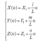
Where: 0≤u≤L, and
In order to analyze the current-carrying conductor of various directions in the substation, the global coordinate and local coordinate are used. At first, a charged segments using local coordinate field calculation, then, by using the coordinate transformation, the local coordinates of the results will be integrated into the global coordinates.
Fig. 1
Model of linear charge element in space
In the local coordinates, the linear charge density can be expressed as
Where: a、b are constants to be determined.
Therefore the potential of the linear charge L at any point in space is deduced as follows
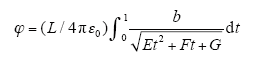
Where: D is the distance from the source point to the field point, if u = Lt, then
From Eq. (3)~Eq. (5), we can get[11]
Where:
In order to save computer storage space and to speed up the computation process. An improved charge simulation algorithm is presented in this paper, which regards the finite length linear charge as constant, the charge density of the two points P1 and P2 are equal

From Eq. (6)、Eq. (7), we can get
When using the improved charge simulation method, the equivalent model is divided into a plurality of finite length segments. The potential coefficient of each linear unit with each matching point is calculated, and the known potential are used as boundary conditions. The equation is given as follows

Where: P is the potential coefficient matrix, τ is the charge simulation column vector, φ is the potential column of the matching point.
Through calculating the charge simulation and division of the conductors, the power frequency electric field intensity of the point P in each directions in space can be derived
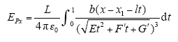
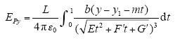
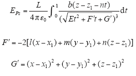
According to the superposition theorem, the electric field strength is generated by three-phase conductor segments, and they are added in sequence in X, Y, Z direction. The electric field strength generated by all conductor segments at point P in each direction is expressed as
Finally, according to the electric field intensity of any point in space in X, Y, Z direction, the total electric field strength E can be calculated
3 The establishment of the modeling of substation
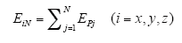
Now taking a 500kV switch yard in the substation as an example for analysis and calculation, the plane configuration of substation is shown in Fig.2. The vertical dashed lines represent position of the set observation lines.
Fig.2
Top view of distribution equipment of 500kV substation
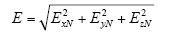
Because of the complexity of the switch yard in the substation. When modeling the distribution of power frequency electric field to calculate its switching field, we make the following simplifying processing: regarding the bus, inlet and outlet lines as linear type wire, potential equal to the wire of voltage, set the ground to be zero potential. The relevant model parameters are set as follow: the height of in-line is 30m, spaced 8m, line height is 26m, spaced 7.5m, 1M, 2M bus modeling height is 16.2m, distance 100m, during normal operation the phase voltage is 303.12kV. The simplified model is shown in Fig.3.
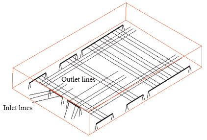
Fig.3
The model of 500kV switchyard Inlet lines
Results and analysis is only considering the overhead line the distribution of power frequency electric field in 500kV switch yard.
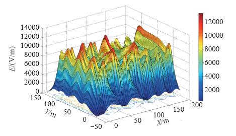
Fig.4
3D distribution of power frequency electric field at the height of 1.5m above the ground inside 500kV switchyard
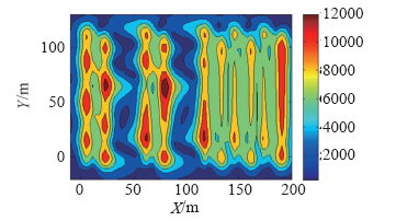
Fig.5
Distribution of power frequency electric field at the height of 1.5m above the ground inside 500kV switchyard
As can be seen from Fig.5 and Fig.6, the field strength of power frequency electric field mostly at 5~9kV/m, less than 12kV/m in the substation. The value of electric field distortion occurs mostly in the outside under in and out line, and by comparing the electric field strength under the three-phase in and out lines, the electric field values are relatively small under the phase B, this is because of the 120° phase lag are arranged in sequence, the electric field strength produced by the middle phase of B three-phase are superposition and offset. The maximum electric field values are concentrated at the junction of the bus and the in and out lines, this is because of the factors that the height of line, conductor structure, the height of electric field point to be calculated lead to the result. The electric field strength even more than 10kV/m in some part area, so in the design phase of the substation, it should avoid the patrol road located in the lager area of the electric field strength as far as possible.
4 The distribution of power frequency electric field in 500kV switchyard with the existence of earth electrode
Wires, isolating switch, circuit breaker, grounding switch and transformers, etc, in the switchyard in the substation are supported by pillars, as shown in Fig.6. These pillars will obviously change the distribution of power frequency electric field. So it is an important way to get close to the actual distribution of power frequency electric field, considering the effects caused by these pillars in switchyard.
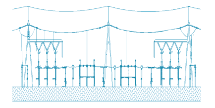
Fig.6
The section of the 500kV switchyard considering the electrical equipment
Due to complex of electrical equipment, the structure of the model should be simplified when modeled, the influence of all kinds of metal earth electrodes in the switchyard on the surrounding electric field mainly is considered. The parameters are set to: the potential of the grounding body is set to 0, the radius of the earth electrodes is set to 0.13m, the metal earth electrodes of the different electrical equipment with different heights (the hight of post insulator is 5.1m, isolating switch is 5.1m, circuit breaker is 4m, grounding switch is 5.1m and transformer is 3.2m). After considering the metal earth electrode the model of 500kV switchyard is shown in Fig.7.
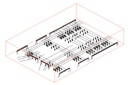
Fig.7
The model of 500kV switchyard considering the earth electrode
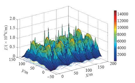
Fig.8
3D spatial distribution of power frequency electric field inside 500kV switchyard considering the earth electrode
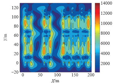
Fig.9
Spatial distribution of power frequency electric field inside 500kV switchyard considering the earth electrode
As can be seen from Fig.8 and Fig.9, the earth electrodes of all kinds of electrical equipment are considered, the power frequency electric field near the earth electrode in the switchyard distort, making the power frequency electric field in the switchyard becomes more and more complex. The maximum electric field value of power frequency is 18.415kV/m in the switchyard which located in the near the earth electrode below the first back incoming line. By comparing Fig.4 and Fig.8, we can get the distribution of the power frequency electric field undergone major change when the earth electrode is considered. The distribution of power frequency electric field is relatively gently (Fig.4 and Fig.5) when the earth electrode is not considered, while considering the earth electrode, the distribution of power frequency electric field of the local peak value appeared more convex (Fig.8 and Fig.9). Obviously, the modeling and the calculation results considered the earth electrode is in good agreement with the actual distribution of power frequency electric field in switch yard.
In order to further study the effect that the earth electrodes of all kinds of electric equipment have an effect on the distribution of power frequency electric field in the switchyard, the electric field of power frequency under the C phase of the first incoming line (the position marked by the vertical dashed lines in Fig.2) were calculated, and the calculation results are shown in Fig.10.
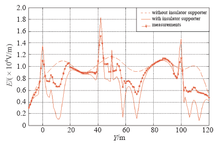
Fig.10
The calculation results of the power frequency electric field with considering the earth electrode or not
As can be seen from Fig.10, after considering the earth electrode, the electric field of power frequency around the earth electrode is subject to greater impact. The earth electrode of electrical equipment makes power frequency electric field occur larger changes, appearing local larger distortion. This is due to the discontinuity of surface normal direction of electric field supported the conductor and the supported conductor is earthed.
5 Conclusion
(1) A more concise three dimensional charge simulation method calculated the distribution of the electric field is derived in this paper, we can use the method to calculate the distribution of power frequency electric field in 500kV switch yard. The efficiency of calculation of this method is higher, avoiding to set the complicated boundaries of the finite element, boundary element method and limit the range of calculation. The calculation results meet the requirements of engineering accuracy.
(2) Considering various of grounding metal holders in 500kV switch yard, thus we establish the calculation model of power frequency electric field in switch yard which include the transmission line, bus and the earth electrodes of all kinds of electrical equipment that is in good with the actual model, we use the method derived in this article to calculate and analysis the distribution of power frequency electric field in switch yard. This work provides an effective, rapid means of researching the electric field distortion around the earth electrodes of all kinds of electric equipment and analyzing of power frequency electric field distribution in the actual substation.
(3) By studying the distribution of power frequency electric field in switch yard that is more close to the actual switch yard, we can find the region that the field strength is stronger and make suggestions of environment security for making an inspection tour in station.
参考文献
Measurement and analysis of power frequency electric field in a 500 kV substation
[J].
The measurement of electromagnetic environment parameters in 500kV substation
[J].
The radial basis data function method for electromagnetic measurement
[J].
Analysis on power frequency electric and magnetic fields within 500 kV substations in chongqing area
[J].The distributions and features of power frequency electromagnetic fields within 500kV substations in Chongqing area are studied. In view of gradually increasing of 500kV substations in Chongqing area, the impacts of power frequency electromagnetic environment within 500kV substations on professional exposure are researched. For this reason, the power frequency electric and magnetic fields in the regions within 500kV substations and in the locations around the power equipments are carefully measured and the measured results are generalized and summarized, and the special regions with higher electric and magnetic field intensity are deeply researched. According to the measured distributions of electromagnetic fields and from the standpoint of occupational safety, the matters needing attention for safety production within 500kV substations are pointed out. Several rationalization proposals concerning safety management of 500kV substations, reasonable disposition and design for new 500kV substations to be constructed and the selection of new substation equipments are suggested.
Electromagnetic environment and corona control measures of UHV substations
[J].
A new 220kV substation surrounding electromagnetic environment monitoring and analysis
[J].
Prediction of stead-state electromagnetic disturbance in UHV substation
[J].
Calculation of power frequency electromagnetic field within substation by moment method and actual measured results
[J].Measurements of electric fields had increased because of public concern about their health effects.This paper introduced the calculation principle of MOM, and gave corresponding formula. Then this method was applied to the calculation of the electromagnetic fields in the 110kV distribution area of Guicheng substation. The comparison of the results and the measurement data showed that it was in this method that the electromagnetic fields in substation can be calculated precisely. Further, this paper presented the measurement data in 100kV-500kV substations in Foshan, which showed that the power-frequency electric field and power-frequency magnetic field in some areas of these substations were both excessive. Therefore, the factors that may make impact on the electromagnetic fields are analyzed, such as the height, space, radius of the lines and soil resistivity, and engineering guiding results were obtained.
Three-dimensional numerical simulation of power frequency electromagnetic field inside and outside substation
[J].The calculation and assessment on power frequency electromagnetic field inside and outside high voltage substation become important increasingly. Combining three-dimensional modeling software Solidworks with electromagnetic field analysis software Ansoft, the three-dimensional numerical simulation of large-scale complicated electromagnetic problem is implemented. Based on the design drawing of a certain 110 kV substation, a three-dimensional simulation model, in which the overhead line, overhead bus, power transformer, building and grounded metal pillar are included, is built by Solidworks software, and then the built model is utilized in Ansoft to perform Maxwell three-dimensional simulation of power frequency electrical field and magnetic field at the height of 1.5 m above ground of the outdoor area of the substation. Simulation results show that the power frequency electric field strength and the power frequency magnetic field strength inside and outside this 110 kV substation are within the limits specified in the standard. At the working corridor, the variation trend of simulation results conforms to the measured results; and in the area where the power equipments are not so intensive, the error between the calculated power frequency electric field strength and the measured power frequency electric field strength is lower than 10%. The proposed method is available for reference to the evaluation and assessment of electromagnetic environment of substation.
Measurement of electric fields around a 1000kV UHV substation
[J].
DOI:10.1109/TPWRD.2013.2269146
URL

This paper investigates the power frequency electric fields around a 1000-kV ultra-high voltage (UHV) substation which is located in Jingmen, China. Detailed field measurements around this substation as well as numerical results in a 1000-kV area are provided. Most values observed are below the reference level indicated in the relevant national design guideline. Therefore, we can conclude that the power frequency electric fields around this UHV substation are safer for working personnel.
Calculation method of power frequency electric field in high voltage substation considering the interference from switching equipment
[J].
Calculation of power frequency electric field near equipment in UHV AC substations
[J].
An effective modeling method to analyze electric field around transmission lines and substation using a generalized finite line charge
[J].DOI:10.1109/61.636926 URL
The effects of the span configurations and conductor sag on the electric-field distribution under overhead transmission lines
[J].DOI:10.1109/TPWRD.2010.2051340 URL